by S.E. Syssoev, A.J. Bartlett, M.J. Eacobacci, Brooks Automation Inc.
EXECUTIVE OVERVIEW
This report summarizes the development of a new cryopump with increased capacity and no short pressure bursts occurring during the cryopumping of type II gases. The new design prevents both possible wafer contamination by uncontrolled intermittent pressure variations inside the high vacuum process chamber, and also the unscheduled shutdown of the processing tool when pressure bursts exceeds certain limits. A 50% higher capacity for type II gas is also achieved with no changes to cryopump external geometry.
One measure of the capacity of a cryopump is established as the quantity of type II gas that can be pumped before the recovery pressure exceeds a specified limit. For a typical physical vapor deposition (PVD) tool, a pressure of 5×10⁻⁶Torr must be achieved within a 5-second interval after the gas flow into the process chamber is stopped (the process is complete).
Figure 1 shows the profile of recovery pressure versus quantity of mixed gas (Ar, N2) pumped by Brooks Automation’s On-Board IS 8F cryopump. During typical process operation (gas flow on), the pressure exceeds the abovementioned level by several decades. At ~800L, the recovery pressure rises, indicating the pump is full and regeneration is required. It is desired by semiconductor manufacturers to have a high-capacity cryopump, ensuring less frequent regenerations, which translates into higher tool availability, improved productivity, and lower cost-of-ownership.
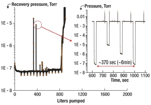 |
| Figure 1. Recovery pressure vs. quantity of gas mixture (Ar-N2) pumped shows the pressure burst problem inside the process chamber. Insert shows that the pump is not capable of reaching base pressure after stopping gas flow, which may be falsely interpreted as a full cryopump indication. |
Yet another challenging task for a cryopump’s designer is also illustrated by Fig. 1. There have been observed well-pronounced pressure bursts that occasionally last for multi-seconds (see inset). The bursts shown are intermittent in nature and can be mostly seen in situations when a cryopump is pumping a sequence of different process gases or their mixture.
Results in Fig. 1 were obtained for a typical PVD process, which can be characterized by ~30 sec long Ar-N2 flow intervals, each at ~1×10⁻³Torr. These pressure bursts resulted in short-term recovery problems and can be interpreted as a "false full" indication, leading to unnecessary regeneration of the cryopump. An additional effect of such bursts can lead to contamination of the semiconductor substrate if the recovery pressure is not achieved before the substrate is moved into/out of the process chamber.
In this report, we explain the development of a cryopump that eliminates pressure bursts and has significantly increased capacity for type II gases in comparison with the same size pump of the previous design [1].
Higher capacity
The cryopumping of type II gases is essentially similar to thick film growth. The gas flow trapped by the pump can be converted into a deposition rate of the gas molecules onto cold surfaces inside the pump. The majority of these molecules form a thick columnar amorphous film, distributed on the cryo arrays. In turn, the thickness of the deposited layer plays a crucial role in the definition of the cryopump capacity, since condensation and retention of these gases are controlled by the available volume for the frost to grow and the maximum surface temperature of that frost. The typical capacity of the pump we’re discussing is ~1000atm-liters (Ar), which can be interpreted as a piece of frost with the following volume:

where V and ρ are volume and density of argon at room and cryogenic temperatures.
Used for condensation of gas molecules, the primary pumping area is directly related to the size of the pump. In the case of the 8-inch (200mm) Brooks Automation cryopump, this area is ~250cm2, which makes the thickness of the frost layer equal to about 4cm. To increase capacity of this size pump, the second stage array should be modified in such a way that the distance from its surface to the entrance aperture of the pump is increased in all directions to ensure not only thicker ice (more gas molecules absorbed) but also that a more uniform distribution of the ice is achieved during normal pump operation. Test results confirming design changes that significantly improve capacity are presented in the following section.
Pressure burst-free operation
The volume of the solidified gas estimated in (1) is interesting to compare with the amount of gas participating in the detected pressure burst. From the first principals, the pressure change is proportional to the mass flow:

where, P — pressure, V — volume, n — number of molecules, R — gas constant, T — temperature, Q — mass flow, S — pumping speed. The total amount of molecules injected during a pressure burst can be found from (2):

The latter allows estimating the volume and (assuming the ice piece is a cube) the side dimension of the cube, which would cause the detected pressure burst in a 50L test system:

This shows that a piece of frozen gas, which is almost six orders of magnitude smaller than the total volume of the trapped gas, could produce the observed pressure spike. To answer the question on why it would happen, one must refer to the cryo-trapping mechanism. As described earlier, the majority of the gas molecules trapped form a thick columnar amorphous film, distributed on the cryo arrays. Because of the pump geometry, however, there are some zones within the pump that are less exposed to the flow, which limits the rate of deposition of gas species inside these zones to a significantly lower level. This low deposition rate and the mobility of the atoms during film growth play a decisive role in the structural formation of the condensate film [2].
Even for the simple argon/nitrogen binary mixture widely used in most reactive sputtering applications in the semiconductor industry, one can expect formation of polycrystalline (or quasi-crystalline) films with a quite complicated crystallographic structure. In two extremes of the Ar-N2 mixture, shown in Figure 2 (after [3]), either structure with comparable large inter-atomic distance (fcc), or the densest, with the shortest interatomic distance structure (hcp), can be formed within a cryopump’s operation temperature range.
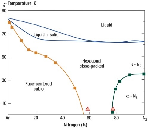 |
| Figure 2. Example of the gas phase diagram, shown for Ar-N2 mixture [2]. |
In turn, quasi-crystalline films formed inside the abovementioned zones of the cryopump, can be a subject to appreciable residual stress due to the presence of structural defects such as misfit, lattice mismatch, porosity, etc. Clearly, the concentration of these defects is affected by operating conditions such as gas species or gas mixture pumped, rate of deposition, and temperature. All of these factors will also lead to significant variations of the film thickness, at some point reaching a so-called critical thickness [4], after which the film exhibits one of the possible cracking patterns — surface crack, channeling, debond.
In conjunction with the solid gas film grown inside the cryopump, residually stressed film can undergo spontaneous delamination [5], resulting in frost flakes being ejected from the cold surface with subsequent sublimation of the flake on warmer surfaces. The duration and magnitude of the pressure burst that could affect recovery would depend on the size and number of the frost flakes ejected, which is uncontrolled and intermittent in nature. This conclusion is not only applicable for gas mixtures used in the processing of semiconductor materials, but for pure gas cryopumped as well. Once the critical thickness of the film deposited on non-primary surfaces inside the cryopump is reached, similar cracking, debonding, and sublimation sequences are expected, resulting in uncontrolled pressure variations in the process chamber.
Engineering solutions, proposed in this work, were aimed at modifying the existing cryopump in such a way that the amount of frozen gas that can accumulate in the low rate deposition areas are suppressed or significantly limited. In other words, even with some deposition occurring, the thicknesses of the stressed films inside the modified cryopump are kept below the critical value necessary to cause delamination and subsequent sublimation.
Test results
The performance of a modified Brooks Automation On Board IS 8F cryopump was evaluated by using an experimental setup consisting of a vacuum chamber, flow meters, and pressure gauges. The flow rates of argon and/or nitrogen were controlled by mass flow meters calibrated at NIST. The pressure inside the chamber was monitored with a fast-response Granville-Phillips ion gauge, calibrated on a separate setup using the methodology described in [6].
A LabView-based test execution routine was used to precisely simulate typical PVD sputtering processes with respect to the amount and duration of the gas or gas mixture to be used during semiconductor substrate processing. To observe the frost formation inside the pump, a vision system [7] was mounted outside the test chamber and was capable of continuously capturing frost formation on different parts of the cryopump.
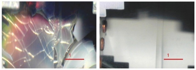 |
| Figure 3. Thin film condensed onto the same non-primary pumping surface: mixed Ar-N2 at ~50L (left, standard design) and ~650L (right, higher performance design) pumped. |
Modification of the 8-inch cryopump was made in such a way that all non-primary pumping surfaces, where gas molecules could potentially be deposited due to the temperature of these surfaces, become almost completely hidden from the gas [8]. As a result, during the time needed to reach the pump’s full capacity, the quasi-crystalline film grown in these zones never reached their critical thickness, and did not debond and subsequently sublime.
Figure 3 shows a comparison of the same zones inside the old and newly designed cryopump. As can be seen, even after ~650 liters were pumped, the cryopump of the new design is almost free from formation of the solid deposits on the non-primary surfaces.
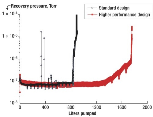 |
| Figure 4. Recovery pressure vs. quantity of mixed gas (Ar-N2) pumped for the cryopumps of standard and higher performance designs. |
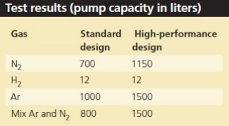
The pressure recovery data presented in Figure 4 demonstrates pressure burst-free operation of the modified cryopump. As predicted, the design changes have also resulted in a significant increase in cryopump capacity for type II gases. The test results shown on the last figure have been achieved using an argon/nitrogen mixture. A summary of all the test data is presented in the table below.
Conclusions
The process of the frost formation inside a cryopump is similar to any thin or thick metal or dielectric film growth — by varying the rate and temperature of growth, one can achieve either a crystal-like structure, or totally amorphous layers. The mechanism of the pressure bursts inside the cryopump discovered in this work is based on delamination of the ice flakes formed on the non-primary pumping surface with subsequent sublimation on warmer surrounding surfaces, which leads to intermittent pressure excursions.
To avoid undesired pressure variations (bursts), formation of highly stressed crystal-like films anywhere on the interior surface of the cryopump needs to be suppressed or limited. Pump capacity strongly depends on the way frost is growing. More uniform distribution of the frost inside the pump leads to increased capacity. In critical semiconductor process applications, the higher capacity maximizes the productivity of the tool by enabling regeneration intervals to be extended to meet the increased operating life of newer targets and/or shields. The modifications applied to this newly developed cryopump are fully transparent to customer processes, providing an exact match for pumping speed, pressure, and time to regenerate with respect to existing product, while achieving the desired performance improvement.
Acknowledgment
The authors would like to thank J.Casello and M.Stira, working for the systems development laboratory, for help in the data collection.
References
1. On-Board IS Cryopump manual, http://www.brooks.com, (2005).
2. M. Layer et al., "Mixing behavior and structural formation of quench-condensed binary mixtures of solid noble gases," Phys. Rev.B 73, 184116 (2006).
3. C. Barrett et al., "Argon-Nitrogen Phase Diagram," J. Chem. Phys., 42, 1, 107 (1965).
4. J. Hutchinson et al., "Mixed mode cracking in layered material," Advances in Applied Mechanics, 29, 63 (1992).
5. H. Yu et al., "Delamination of thin film strips," Thin solid films, 423, 54-63 (2003).
6. K.M.Welch et al., "Recommended Practices for Measuring the Performance and Characteristics of Closed-loop Gaseous Helium Cryopumps," JVST A, 17(5), (1999).
7. Keyence Corporation of America, Unit selection catalog, (2006).
8. A.J.Bartlett et al., "Pressure burst free high capacity cryopump," U.S. Patent Appl. 20080168778, (2008).
Biography
Sergei E. Syssoev received his MS in engineering from St.-Petersburg State Technical U., and a PhD in physics from A.F. Ioffe Institute of Physics and Technology, Russia, and is chief scientist at Brooks Automation, 15 Elizabeth Dr., Chelmsford, MA 01824 USA; [email protected].
Allen J. Bartlett received his formal education at Wentworth Institute and Northeastern U., and is a senior staff engineer at Brooks Automation.
Michael J. Eacobacci received his BSME and a MS in materials science from Northeastern U., and is director of applications engineering at Brooks Automation.

