By Dave Rose, Keithley Instruments, Inc.
February 14, 2011 — Thorough characterization of any material or device requires precision DC, AC impedance, and ultra-fast I-V or pulsed I-V measurements. Test equipment connection to a semiautomatic or manual probe station can be complicated. If performed incorrectly, it could diminish on-wafer measurement accuracy. This article addresses specific cabling techniques for DC, multi-frequency capacitance, and ultra-fast I-V and pulse testing, as well as the importance of proper grounding and shielding, choosing the proper interconnect for a specific measurement, and troubleshooting common interconnect problems.
Cabling for DC measurements: Potential error sources
Understanding anticipated measurement levels makes it easier to assess potential error sources. For simplicity, let’s assume that all of the signals being measured are neither high voltage (i.e., greater than 100V) or high current (greater than 200mA). We can break down the error sources into three categories: leakage currents, electrostatic interference, and mechanical effects.
Leakage currents. Leakage currents are currents flowing through paths other than the intended signal paths, for example, current flowing through the interconnect insulator. This leakage current can be a problem when the device under test (DUT) impedance is similar to that of the various insulators in the circuit. The simplest fix is to use a high quality cable with a high resistance insulator such as Teflon or polyethylene. Better cables can often reduce the effects of dielectric absorption, which is also a function of the insulator material.
 |
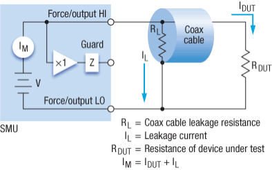
| Figure 1. Leakage current flows through the cable’s insulation resistance. |
Although using quality cables can go a long way toward reducing leakage currents, it may not always be sufficient. It’s important to understand what happens when a typical DC instrument, such as a source-measure unit (SMU), is connected to the DUT using a coaxial cable. In Figure 1, a leakage current (IL) flows through the cable’s insulation resistance (RL). This causes the SMU to measure the sum of the current flowing through the DUT (IDUT) and the leakage current, rather than just the current flowing through the device.
Guarding can eliminate the effects of leakage currents flowing through the insulator. A guard is a low-impedance point in the circuit that’s at the same potential as the high-impedance lead in the circuit. In a guarded measurement, because the shield is driven to the same potential as the force high terminal of the SMU, no current flows through the insulation resistance, eliminating leakage current effects.
 |
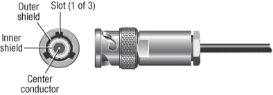
| Figure 2. Triaxial cable |
Guarding requires a third connection on the test instrument in addition to the shield and signal conductor. Although it’s theoretically possible to use a guarded connection on a coaxial cable, it would be unsafe because the shield would be at the same potential as the force terminal. The SMU guard should never be connected to the shield of a coaxial cable. However, using a triaxial cable solves this problem because it has two shields: an inner shield to which the guard is connected, and an outer shield that is connected to low terminal (Figure 2).
Electrostatic and magnetic interference. These kinds of interference occur when electrically (or magnetically) charged objects disturb the circuit under test. Although these effects are negligible at low impedances because the charges dissipate quickly, that doesn’t hold true at high impedances. Typically, electrostatic interference sources are environmental, such as fluorescent lights, motors, and even people. Electrostatic interference-induced errors are generally due to some type of capacitive coupling into the circuit, which can create an extra current defined by this equation: 
Errors due to electrostatic coupling can be minimized in two ways. The first is to use shielded triaxial cables. Another is to connect the prober’s head plate, dark box, or metal enclosure to ground, so the induced current noise will flow through the shield to ground and not through the DUT.
Although grounding the prober’s enclosure or head plate is a good way to reduce electrostatic interference, doing it poorly can make matters worse. Typically, the prober and instrument are connected to two separate power line grounds because they are usually connected to separate power outlets. In that set up, a fluctuating current can flow between the instrument and the probe station, causing the instrument’s ground unit or low connection to move, producing errors. These are known as ground loops; to prevent them, the prober enclosures and shield should be connected to a common point.
Mechanical effects. Triboelectric and piezoelectric effects are also significant sources of DC measurement errors. Triboelectric currents are generated by charges created by friction between a conductor and insulator: free electrons are rubbed off the conductor, creating a current charge imbalance that generates current flow. This effect is noticeable when low quality cables are flexed. The insulators of high-quality cables are usually coated with a lubricating layer of graphite, which minimizes friction. Even high-quality triax cables need vibration isolation, which can cause some current flow due to piezoelectric effects. Placing a prober on an air table and using remote pre-amps to minimize the triax cables’ length can help minimize these problems.
 |
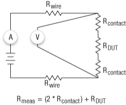
| Figure 3. Kelvin (four wire) connection |
Losses due to two-wire connections. No matter how good the cable is, losses through it can still be significant. The resistance of most interconnect cables is only a few ohms for even a very long length of cable. However, when the resistance of the DUT is also relatively low (e.g., a metal structure), and the instrument is connected to the DUT using two-wire connections, the resistances contributed by the cables and pad contacts can cause large errors. For example, if the resistance of the cables, contacts, and DUT are single ohms, then the meter will measure the sum of these resistances. Fortunately, four-wire or Kelvin connections (Fig. 3) offer a way to solve losses due to drops across the interconnect. In a Kelvin connection arrangement, a voltmeter is connected across the DUT. The instrument can force current and measure the voltage drop across the DUT. In this case, given that the voltmeter has a high impedance, very little current will divert to the voltmeter. Therefore, the forced current is essentially the same at all points in the circuit and the voltmeter will measure only the voltage drop across the DUT plus the contact resistance, not the resistance of the interconnect cables.
Cabling for C-V measurements: Potential error sources
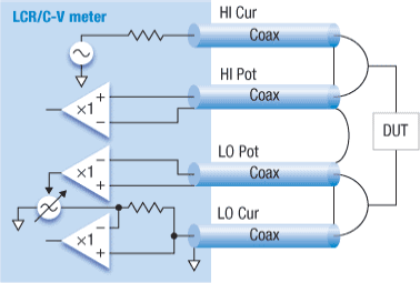
Semiconductor capacitance (C-V) measurements are typically performed using a multi-frequency capacitance meter (Fig. 4) with four terminals: high current (HI Cur), high potential (HI Pot), low current (LO Cur), and low potential (LO Pot). These terminals are coaxial, so they normally require a coaxial interconnect cable. They also have a fixed characteristic impedance, typically 50 or 100ohm. A multi-frequency capacitance meter measures impedance by sourcing a small AC voltage across the DUT and measuring the resulting AC current and AC voltage.
 |
| Figure 4. Multi-frequency capacitance meter with 4 terminals. |
The signals used to measure capacitance are AC, so take care that the signal paths minimize impedance changes. Changes will generate signal reflections that can impact the AC source and measure signals, causing erroneous readings. A good technique is to use cables with the same characteristic impedance as the instrument. Also, most capacitance meters perform some form of cable compensation, which involves entering the cables’ lengths into the meter set up. All four cables must be the same length to minimize impedance changes in the signal path and ensure the meter’s cable compensation calculations are correct.
Improperly shielded coaxial cables can also cause errors in capacitance measurements, so check that the cables’ shields are not open.
Stray cabling and interconnect inductances can cause resonances in the test circuit, producing erroneous capacitance measurements. Reduce the inductance by connecting the shields of the coaxial cables as closely as possible to the DUT, isolating the inductance from the measurement.
Cabling challenges for ultra-fast DC and pulse measurements
These measurements involve signals in the AC or high-frequency domain, which requires a different approach and considerations than for DC or C-V measurements.
Fourier series analysis shows that, no matter the speed of a pulse, it can be modeled as a series of sinusoids of varying amplitudes and frequencies. If the signal path can’t pass higher frequencies accurately, some fundamental frequencies are affected, distorting the shape of the pulse and affecting the power transmitted to the device. Therefore, pulse testing requires a signal path with a higher bandwidth requirement (approximately 150MHz) than either DC or C-V testing.
Pulse generators don’t typically include measurement capabilities, and oscilloscopes don’t source. The connections are single-ended; the center conductor carries the signal and is connected to the DUT. The shield of the coaxial cable is the return path for the signal and ideally should be connected to the low terminal of the DUT. A new class of pulse instruments does offer measurement capabilities, but even these instruments use a single coaxial cable to the probes for each channel. To prevent reflections, the interconnect’s impedance should match that of the source. Most pulsing instruments have a 50ohm input impedance, so one normally uses 50ohm coaxial cables to connect to the instrument. To minimize inductances, it is a good practice to connect the shields of multiple coax cables together.
To ensure the entire signal path is free of impedance changes or insertion losses, ideally, the shield of the coaxial cable should be connected to the low side of the test circuit. And while connecting the low side of the DUT to DC ground will work, the return signal now may follow two paths back to the instrument: one through earth and the second through capacitive coupling to the coaxial shield. Connecting the low side of the test circuit to a DC return path will ultimately limit the fidelity of the pulse.
|
DC I-V measurements:
|
LCR/C-V measurements:
|
Pulsed I-V measurements:
|
Different measurements; different cabling requirements
As the table outlines, each measurement type has its own cabling requirements. Testers must change the prober cabling between DC I-V, C-V, and pulse testing on a DUT, especially if no switch matrix is being used. Changing cables can be time-consuming and often requires raising and lowering the probes between tests, which risks damaging the wafer pads. A new multi-measurement prober cables (MMPC) kit optimized for use with Suss and Cascade probers offers a simple solution to this problem and supports I-V, C-V, and pulsed measurements using a single set of triax interconnects. Keithley’s MMPC cables are special triaxial cables and adaptors that allow both high-precision DC and high-bandwidth AC connections to the probes and DUT. The cables can be arranged in Kelvin and non-Kelvin configurations. Set-up can be done without disturbing the cabling to the probes; only the cables at the prober connector bulkhead are moved. Keithley’s Model 4225-RPM Remote Amplifier/Switch, a companion to Keithley’s 4225-PMU Ultra-Fast I-V Module, automates reconfiguring MMPC cables when using the Model 4200-SCS Semiconductor Characterization System.
Dave Rose is senior staff applications engineer, Keithley Instruments Inc. Contact him at ph. 440-498-3040; [email protected]; Keithley Instruments, Inc., 28775 Aurora Road, Cleveland, OH 44139. For details on the transmission line concepts that underlie this interconnect approach, download a copy of Keithley’s white paper on the topic, "Labs’ Demands for Greater Measurement Flexibility Require Cabling Systems Capable of Accommodating Multiple Measurement Types," available at http://www.keithley.com/data?asset=52554.
Subscribe to Solid State Technology/Advanced Packaging.
Follow Advanced Packaging on Twitter.com by clicking www.twitter.com/advpackaging. Or join our Facebook group

