by David Blaker, VP of engineering and manufacturing, siXis Inc.
October 26, 2009 – As the expense and risk of ASIC development have risen consistently with the advance in deep submicron technology (Figure 1), the number of design starts has dropped more than 50%, from 7,749 in 2000 to 3,196 in 2007 [1], and continues to fall [2]. The cost of a new ASIC development has become prohibitive for most products that have volumes less than 1M units per year.
The availability of ASSPs, programmable logic, CPLDs, FPGAs and MPUs with extensive peripherals has contributed to this trend by allowing system designers to substitute firmware development for hardware development; development cost and schedule are reduced by overlapping hardware and firmware design and replacing hardware build cycles with compile/test/debug cycles. FPGA design starts now exceed ASIC design starts by 30:1 [3]. This trend greatly reduces the risk and expense associated with ASIC design but fails to address the needs for lower size, weight, and power.
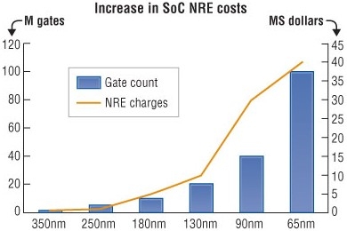 |
| Figure 1. NRE costs by process geometry (Source: Semico Research Corp.) |
Integration limits
The level of integration that can be obtained in monolithic silicon has both economic and technical limitations. Advanced lithography optics don’t support die larger than approximately 28mm on a side (Figure 2, the line labeled reticle limits). The cost of a die also increases geometrically as the die size approaches the limit due to decreasing number of larger devices on a fixed area wafer and decreasing yield per device due to defect density. Also, integrating different technologies multiplies device cost by applying processing steps to device area that doesn’t require that step (e.g., by integrating DRAM into logic devices).
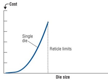 |
| Figure 2. Economic and technical integration limits |
Memory bandwidth
High-speed serial interfaces are rapidly replacing parallel interfaces in large logic devices because of reduced pin counts, higher data throughput, and robustness. Supporting these higher throughputs, however, requires ever-higher memory depths and bandwidths to buffer those interfaces (Table 1).
 |
| Table 1. Memory requirements for high-speed interfaces |
The memory bandwidth required is twice the data throughput because each bit buffered must be both read and written at least once. The number of pins required is increased by 25% to approximate a 20% overhead (for example, due to refresh accesses and row precharge cycles). Large BGA packages are generally limited to about 1,900 pins because of co-planarity issues in soldering these packages to an FR-4 substrate. Higher bandwidth serial interfaces require more power and ground pins to isolate these interfaces from noise generated by other I/O pins. This then reduces the number of pins available for memory interfaces.
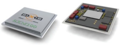 |
| Figure 3. Embedded computing module with and without lid |
SiCB technology
siXis Inc. develops, manufactures, and markets embedded computing modules employing SiCB (silicon circuit board) technology. A flip-chip attaches bare die devices to a large-area passive silicon substrate (Figure 3), shrinking the subsystem size by a factor of 2 to 3 (Figure 4). For instance, an FPGA can be combined with 1GB of DRAM. This level of integration will not be available in monolithic silicon for years and will be prohibitively expensive (Figure 5).
Eliminating an extra layer of packaging reduces the parasitic interconnect capacitance, reducing the module system power on the order of 22%.[4]
 |
| Figure 4. SiCB solution for economic and technical integration limits |
This approach allows integration of tested devices from different wafers fabricated in different facilities with different processes, without modification. NRE expenses for ECMs employing SiCBs are in the range of $100,000s, up to two orders-of-magnitude less expensive than SOCs. The SiCB contains only interconnect without any active devices. A complete design cycle from requirements to prototypes is on the order of 6 months. This compares favorably with SOC designs that can take 18 months or more, especially considering the risk of multiple design/fabricate/test cycles.
Since the signals connecting the devices on the SiCB are contained within the SiCB, package I/O limitations are avoided, allowing integration of large, high-speed parallel memory busses in the ECM without increasing the package I/O count beyond practical limits. This has the additional benefit of significantly reducing the complexity of the PCB to which the ECM is attached. For example, in Fig. 5, the number of signal pins soldered to the PCB is reduced 4× with an ECM.
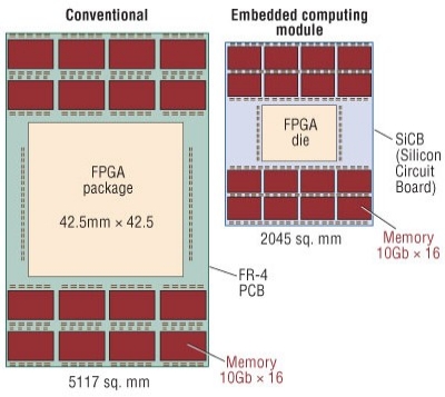 |
| Figure 5. Area savings for embedded computing modules employing SiCBs |
Comparison with 3D integration
3D integration of multiple semiconductor devices has been an area of active research for more than 10 years.[5] Much recent work has focused on using through silicon vias (TSVs) to stack die one on top of the other. Despite the effort expended, only one commercially available product is shipping today using TSVs (a CMOS Image Sensor (CIS) from Toshiba [6]).
A major shortcoming to this approach is thermal management. DRAMs are very sensitive to temperature and run at lower junction temperatures than high-performance logic devices, such as FPGAs or processors. Stacking memory devices on top of logic devices creates a thermal problem that is currently unsolved. Spreading the devices with SiCB integration avoids this problem.
3D stacking also requires modifying standard devices by adding TSVs, which requires detailed design information from the device manufacturer–information that is usually closely held. The siXis approach uses standard bare die with no modification. All of the new interconnect is contained in the SiCB, easing the supply chain issues associated with obtaining bare die.
Comparison with MCMs
MCMs are multi-chip modules, generally built on ceramic substrates. They are limited by the feature sizes possible in ceramic technology to packaged devices or wire-bonded bare die. This limits the achievable integration and performance below the level reached by ECMs built with SiCB technology (Table 2).
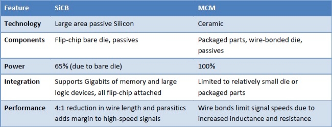 |
| Table 2. ECM/SiCB Comparison with MCM |
Conclusion
ECMS employing SiCB technology are an alternative to expensive ASIC developments, with advantages in performance and power for integrating memory and logic. They are also a practical alternative to 3D integration, which remains a technology of the future due to thermal and supply chain issues. These advantages are accompanied by a reduction in the complexity of underlying PCB designs, saving additional NRE expenses and risk, and reducing time to market.
Biography
David Blaker is vice president of engineering and manufacturing at siXis Inc., 3021 E. Cornwallis Road, Research Triangle Park, NC USA; 919-248-9193, e-mail: [email protected].
References
[1]. According to Gartner, as reported in EETimes March 26, 2007, "Sockets scant for costly ASICs"
[2]. EDN March 30, 2009, "ASIC design starts to drop 22% in 2009, Gartner reports"
[3]. Ibid.
[4]. siXis Inc., Whitepaper: Power Savings of Embedded Computing Modules (ECMs) over FR-4 Implementations Rev. A, 8/09
[5]. "Implementation of a Gallium Arsenide Multichip Digital Circuit Operating at 500-1000 MHz Clock Rates Using a Si/Cu/SiO MCM-D Technology", IEEE Transactions on Components, Packaging, and Manufacturing Technology — Part B, Vol. 20, No. 1, February 1997, pages 17-26
[6]. SEMICON West 2009, multiple presenters

