Category Archives: 3D Integration

by Dr. Philip Garrou, contributing editor

October 4, 2010 – The recent SEMICON Taiwan 3D Technology Forum (Sept. 9) shed some insight into what several foundries, assembly houses and customers are thinking about the timing for 3D interposers and full 3D IC.

Dr. Ho Ming Tong, GM and chief of R&D for ASE, commented that he expects the commercialization of interposers, what’s being called 2.5D, to arrive "in two years" and that interposers "will not be a simple transitional technology…[but will allow] the smooth transition from 40nm to 28nm." Concerning full 3D IC, he expects to see large-scale implementation "in three to five years." Others have interpreted these remarks as an indication that ASE has pushed back full 3D IC several years from their previously released roadmaps. After checking with ASE, it appears that the comments should not be taken as a slowdown in the ASE roadmap, but rather an indication of when 3D IC will be used in a widespread manner.

Kauppi Kujala, senior technology manager for Nokia, indicated that the company has been using devices with through-silicon vias (TSV) such as MEMS microphones and CMOS image sensors since 2006 and 2007, respectively. "For memory stacking, TSV can offer clear miniaturization opportunities and also [higher] performance and power reduction," he noted. He expects to see 3D silicon interposers "soon," driven mainly by low-k mechanical limitations. These will be single-chip packages, i.e., the chips will be bonded to a silicon interposer which will subsequently packaged in a standard package such as a BGA.

(Source: Nokia)

Kujala predicts wide-bandwidth memory on logic 3D IC stacks will be available 2012-2013, noting that "costs will be critical and standards still need to be put in place." Nokia’s first target for a wide IO package will be a package with four DRAM chips, targeting high-end smartphones and later migrating to mid-segment and lower-category phones. Nokia expects wide IO standards will be ready in late 2011.

Qualcomm’s Nick Yu, VP of engineering, also sees smart phones driving their interest in 3D IC. Yu emphasized that increased activity in standards is needed to mitigate risk and simplify the supply chain.

Shan-Chieh Chien, VP of advanced technology development at UMC, called 3D stacking with TSV the "big elephant" technology for foundries. UMC, which recently announced an alliance with Elpida and Powertech, commented that logic + wide IO DRAM stacking will occur in 2011-2012 consistent with the comments of Nokia and others. UMC also sees a significant future for silicon interposers with and without integrated passive components.

Carl Chen of Siliconware’s R&D group emphasized SPIL’s interposer 2.5D solutions, and showed their roadmap which calls for interposers late this year and memory stacking in 2011-2012:

TSV technology roadmap. (Source: SPIL)

A compilation of recent roadmaps from these and other major players shows a consensus on the commercialization timing expected for 3D IC.


Dr. Phil Garrou is a contributing editor for Solid State Technology and Advanced Packaging, and a frequent blogger with his Insights from the Leading Edge.

Steve Lerner, Alchimer S.A., Massy, France

Consolidation has been a mega-trend in the chipmaking world in recent decades. Dozens of EDA companies have been started and then acquired by the biggest two or three firms. Where there were once a half-dozen leading-edge lithography companies, now there are two – about the same number of leading players as most sectors of the equipment market.

This trend towards fewer, larger suppliers was predicted by many observers. It’s a function of the maturation of the semiconductor industry, as well as formidable barriers to entry into it. Among these barriers are long sales cycles (it can easily take five years for a tool to go from initial design to real revenue), the need for global support and service, and the very limited number of potential customers.

From a top-level business perspective, it’s worked out reasonably well. Chipmakers are designing and producing chips, equipment companies are starting to sell equipment again, and iPhones and DVRs are flowing nicely.

But from a more front-line perspective, there is cause for concern. Take the example of through-silicon vias (TSVs). This emerging technology is widely accepted as a basic enabler for current and future device generations, and also for the industry’s advance into the "More Than Moore" space, where electronic devices will go beyond raw computing power to incorporate sensors, wireless networking, and battery-free power.

If you’re a well-established supplier of chipmaking equipment or design software, you certainly want to play in the TSV market – but you want to do it in the way that’s most beneficial to your company’s bottom line. Very often, the best risk-reward combination is to adapt existing technology for a new application, rather than starting with a clean sheet of paper and identifying the best approach. As the risk of competition from startups decreases, the rewards of keeping R&D investments low increase. This is what we’re seeing in the TSV sector – and it’s starting to have negative effects on the industry’s ability to adopt TSV technology.

Today, the supply chain is trailing ITRS expectations for TSVs. While it’s possible to produce TSVs with an aspect ratio of greater than 20:1, circuit designers, always mindful of device manufacturability and cost, are limiting their designs to ratios of less than 10:1 to maintain compatibility with existing dry deposition processes.

Common sense tells us that device packaging should be relatively inexpensive, compared to front-end processing. But the available equipment for TSV production is very pricey because it was designed for dual damascene or MEMS applications, and there are insufficient incentives for the existing equipment leaders to redesign the equipment or lower its cost.

There are historic parallels to this issue, particularly bumping and wafer-level packaging. For years, wafer bumping was seen as a high-benefit solution for wafer-level packaging, but a lack of infrastructure was partly to blame for its slow adoption by offshore assembly and test houses. They couldn’t afford the equipment that IDMs were using for bumping. Smaller equipment makers, seeing the opportunity, eventually stepped in and provided that missing link in the supply chain with lower-priced deposition tools.

Something along these lines will happen with TSVs; the free market has a way of reconciling these mismatches. Yes, it takes more time in a highly consolidated market with steep barriers to entry. But that slowness creates ever-increasing opportunities for the packaging suppliers who want to be the first to offer high-aspect ratio TSV technology, and the suppliers who can help make it economically practical.

Steve Lerner is CEO, Alchimer S.A., Massy, France,  [email protected].

More Solid State Technology Current Issue Articles
More Solid State Technology Archives Issue Articles

(September 13, 2010) — Package-on-package (POP) devices present some unique challenges with respect to the rework process: one of these is how to rework an underfilled package; also, these packages are prone to warpage. Lastly, the challenge of inspecting the area array devices can be overcome with highly trained personnel with experience in the BGA rework area. Bob Wettermann, BEST Inc., discusses rework solutions.

Stacking semiconductor packages suits various applications requiring smaller footprints, greater functional density, and higher performance. Consumer products using flexible package design include digital cameras, portable game players, GPS products, and smartphones. When these devices need to be repaired or upgraded or reworked, PoP packages require a robust, cost-effective, reliable rework process. This article discusses rework solutions.

PoP packages present some unique challenges with respect to the rework process: one of these is how to rework an underfilled package; also, these packages are prone to warpage. Lastly, the challenge of inspecting the area array devices can be overcome with highly trained personnel with experience in the BGA rework area.

Underfill

The rework of underfilled POPs is a major challenge as most of the underfill materials are epoxy-based. These epoxies need to be heated above their softening temperature (above 150°C) and along with this heat a mechanical force needs to remove this previously cured material. The material removal can be accomplished through high temperature vacuum extraction or hand tools, depending on the modulus of elasticity and underfill’s softening temperature.

The most commonly used underfill rework process begins with even substrate heating to a temperature above the underfill’s softening point. The package is mechanically gripped or pried with enough torque to break the fillet’s adhesions to the PCB. The chip undergoing rework is then heated above the solder reflow temperature to melt the solder connections and break the softened underfill. The device is removed from the PCB and residual solder and underfill cleaned off the substrate. Cleanup after chip removal removes any underfill, as well as excess solder on the substrate. This part of the process must be done with extreme care so as not damage the pads and adjacent components on the substrate. The site is then cleaned prior to inspection. Once substrate cleanup is complete, a new chip can be aligned, reflowed, and underfilled. The manual nature of this process — both heat and mechanical forces being used — results in less than a 50% yield in the best of cases.
Click to Enlarge
Figure 1. Warped package-on-package (POP).

Warpage

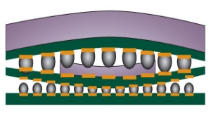
POP packages, due to their thin construction, are subject to warpage during initial assembly as well as rework. During the package-to-board placement process, if the lower package substrate flexes downward at its edges the solder ball contacts mating with the PCB can collapse to the point of collapsing together and creating a shorting condition (Fig. 1). Similarly, if the second-level package substrate warps in the opposite direction of the lower package, the solder will elongate and possibly separate.

Inspection and X-ray

Most contract rework houses or assembly houses have 2D X-ray as part of their normal non-destructive process control measures. By reviewing the ball diameters for consistency, problems in the rework process can be discovered. The trick is to make sure that the actual images being reviewed are all at the same layer. This can be difficult with a transmissive X-ray as the exact location of where the ball images show up in the Z-axis is difficult to confirm. All of the device layers are seen at the same time in the same X-ray image, so lower layers can be obscured by upper layers.

In some X-ray systems, oblique angle views (tilting the part or tilting the X-ray source) may be useful, but only to a limited extent. Layers placed further away from the X-ray tube will be seen as smaller than the closer layer; this phenomenon (known as geometric magnification) coupled with the different ball diameters of the different layers makes for very confusing X-ray images. Even when using a laminographic method (i.e., “slicing” of different x-ray image layers), there is not the resolution required to determine which ball sizes are to specification and which are not.

The challenges of inspection, part warpage and underfill removal without part all complicate the rework of POP devices. There are a few different methods being used to the rework process.
Click to Enlarge
Figure 2. Stacking one layer at a time method of POP rework.

Different rework methods

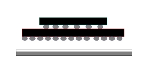
There are two basics processes being used in the rework of POPs, namely: a “stack” of the multiple layers is pre-made and the device is then placed like a standard area array device (Fig. 2 “Stack one layer at a time”); or the first layer of the stack is placed onto the board and then the subsequent layer(s) of the stack are placed on top of the first. In either case, accurate and repeatable placement accuracy, the right materials, and tight process controls, are required to generate first pass yields over 95%.

Stack rework method. In the stack method, the devices are first assembled together and then placed as a single entity on the board location to be reworked. Starting with the package that is closest to the base package (the one that will be soldered to the PCB), solder paste is dipped into a reservoir to a depth of 40-50% of the ball diameter. The solder paste volume is controlled by ensuring that the reservoir is filled prior to each “dip” and that the depth to which the package is submerged is tightly controlled. Many rework stations can control this depth by having it “bottom out” in the reservoir. The nozzle then places the package on top of the base device. Finally, the stack is reflowed, cleaned and inspected. These steps are repeated for any subsequent packages that need to be placed onto the stack. Once the stack has been completed, the last step is attaching this “stack” to the PCB. Paste printing with either a removable stencil, or, for greater paste volume and prevention of shorts, a stay-in-place polymide stencil may be used to attach the stack to the PCB.

Layer rework technique. In this rework technique, each layer of the stack is individually placed one after the other beginning with the device being attached to the PCB, stacking the layers until all of the PoP elements have been placed. For the base layer, the PCB is paste-printed using either a peel-and-release type of stencil, or a stay-in-place polyimide stencil. Subsequent packages can have either paste flux or dipping solder paste applied, be aligned to the next layer in the stack, and then placed. Once all of the layers have been placed, the entire stack is reflowed. The benefit of this approach is that the die are only exposed to a single reflow and intermetallic growth in other layers is limited, increasing the probability of good device reliability.

Rework materials

There are several types of soldering materials that are recommended for use in the rework of POPs: solder paste, newly developed “dipping” pastes or fluxes, or paste flux.

Solder dipping paste used in the dipping process has different rheological properties than paste used for standard surface mount assembly. The dipping paste is lower in viscosity than that designed for printing or dispensing. Pastes with 75-80% metal content and type IV particles (20-38µms in diameter) work best for dipping.

Fluxes used in POP rework also have modified properties when compared to the standard BGA rework paste fluxes. The typical POP flux is a water-soluble, no-clean formulation containing a mild- to medium-active organic acid. When formulating tacky flux, suppliers must balance viscosity and elasticity so the material can be spread in a flat, even film for dipping. If the material is too thick, the film will have streaks or voids. If it’s too thin, the film won’t hold its shape or maintain an even thickness over time.
Click to Enlarge
Figure 3. Dipping paste used to attach one layer on to next.

Dipping process for POPs

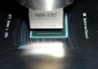
When “dipping” style fluxes and pastes are used in the rework of PoPs the rule of thumb is to dip transfer 40% of the ball diameter (Fig. 3). Compared to the printing process, dip transfer techniques transfer less solder paste volume. The dip method has a smaller process window compared to the printing process, and is therefore more susceptible to yield detractors, including poor dipping volume control for heavier parts and incorrect paste flux tack properties. The data implies that you are only likely to see an issue with the pick up PoP components from a dipping PoP flux tray if components are too heavy, if the vacuum nozzle is too small, or the flux has high tack properties.

In cases where underfills need to be applied underneath the device package, flux will not work. Since the lack of cleaning under the package prevents the underfill material from spreading completely there, flux is not recommended.

PoP rework recommendations

To overcome the numerous POP rework challenges, proper process techniques using good process control methods must accompany these materials.

There are several precautions you can take during POP rework to overcome warpage effects. One of the recommendations is to use a solder paste when placing the entire “stack” onto the board, or even in between the various layers. On the board location, this paste printing is recommended for maximum solder volume application. In between stacks, a “dippable” Fig. 3 solder paste can be used to increase the solder volume in the solder joint and therefore insure a greater process window. Finally, one can use a polyimide stay-in-place stencil that allows both a greater, more consistent volume of solder paste to be printed, and prevents the shorting of balls as a dielectric barrier is formed around each of the balls. These rework methods can be used to help overcome the negative impacts of POP package warpage during the rework process.

When attempting to rework a POP that has been underfilled, this very labor-intensive, low-yielding process many times makes the rework process undesireable. The epoxy and other material underfills require the use of both heat and mechanical force to remove. This combination ultimately either damages the part or the board, creating either more repair, or causing the board to be scrapped. Therefore, extreme dexterity of the rework operator is required to overcome this challenge.

There are challenges in inspecting a POP device after the rework process has been completed. For instance, some balls are “hidden” behind others in the x-ray image, or the inspector may be confused on which ball is on which layer. This problem can be somewhat mitigated by oblique angle views on the x-ray system. While not seeing all of the layers completely clearly, oblique angle viewing will have the propensity to show defects such as head in pillow (HIP) failures, and clearer indication of any opens.
Click to Enlarge
Figure 4. POP post-rework.

Conclusion

There are numerous rework challenges associated with POP devices. The problems of part warpage, proper inspection post-rework, as well as the rework of underfilled devices, are certainly challenging. They can be overcome to a great degree by using the proper materials; methods; and highly trained, skilled rework technicians.

References
[1] R. Boulanger, “Assembly Challenges of Package-on-Package,” Proc. of SMTA International Conf., 2006, pp.338-341.
[2] P. Wood, “Reworking Package on Package Components,” Proc. of SMTA International Conf. 2007, pp.363-367.
[3] L. Smith, M. Dreiza, A. Yoshida, “Package on Package (PoP) Stacking and Board Level Reliability Results,” Proc. of SMTA International Conf. 2006, pp.306-312.
[4] H McCormick, I. Sterian, J. Chow, M. Berry, J. Trudell, R. Cortero, “PoP: An EMS Persepctive on Assembly, Rework and Reliability,” Proc. of SMTA International Conf. 2008, pp.102-113.

Bob Wettermann received his BSEE University of Illinois, MBA DePaul University and is QC Manager at BEST, 3603 Edison Place, Rolling Meadows IL 60008; ph.: 1-847-797-9250; [email protected]

Follow Advanced Packaging on Twitter.com by clicking www.twitter.com/advpackaging. Or join our Facebook group

(September 1, 2010) — The 17th Annual International KGD (Known Good Die) Packaging and Test Workshop 2010 will focus on semiconductor die products test, assembly, manufacturing, and business issues in the microelectronics industry. Bill Bottoms will keynote, covering deep submicron and 3D integration.

Co-organized by SEMI and TechSearch International, the workshop’s theme this year is “Challenging Issues for KGD as the Industry Moves to Finer Geometries.” The event is set for October 28-29 in Austin, Texas. Visit our events homepage here.

Keynote presenter Dr. Bill Bottoms, chairman and CEO of Third Millennium Test Solutions and chairman of the ITRS Roadmap Committee, will present on “Known Good Die in the Era of Deep Submicron and 3D Integration.” Workshop presenters represent companies including: Aehr Test Systems, Analog Devices, ASE Group, Galaxy Semiconductor, Infineon, Muhlbauer, Nanya Technology, PARC, Pintail Technologies, Ridgetop, Rudolph Technologies, SavanSys Solutions, Schweizer Electronics, Semilab, STATS ChipPAC, and 3M. A special panel will explore a related topic of “Is KGD Required for TSV?” moderated by Jan Vardaman of TechSearch International.

Follow Advanced Packaging on Twitter.com by clicking www.twitter.com/advpackaging. Or join our Facebook group

KGD Workshop sessions include:

  • Small Problems — Big Solutions: with presentations on Junction Leakage Degradation; Fine Pitch Copper Wire Bonding Implementation Down to Deep Submicron; and Scalable Microspring Contacts for Integrated Test and Packaging
  • Process Improvements: Test Process Control —- Real-Time, Automated Methods to Improve Yield and Lower Cost; Introduction to Protocol-Aware ATE; and Cost vs. Reliability Tradeoff for Stacked Devices
  • KGD for Embedded Solutions: KGD Cost Modeling for Embedded Products; Chip Embedding into PCB Substrates Without KGD; KGD for Embedded Products; and LED Test and Packaging Challenges: A User Perspective
  • Wafer Sort and Handling Improvements: Wafer Sort Methods Employed to Achieve Automotive Customer’s Zero ppm Requirements; New Advancements in Ultra-Thin Die Handling and Flip Chip Inspection; and Rapid Deployment of IC Solutions

The workshop brings together technical experts, managers and business development professionals from around the world for an interactive exchange of information on the latest developments in the die product industry.

For more information on the KGD Packaging and Test Workshop, visit www.semi.org/en/EventsTradeshows/ctr_028107.

(August 31, 2010) — Peter Ramm, Fraunhofer EMFT, will be the Opening Speaker at the 7th Annual International Wafer-Level Packaging Conference (IWLPC). The IWLPC will be held October 11-14, 2010 at the Santa Clara Marriott Hotel in Santa Clara, CA. Visit the events page here.

Ramm will present "The European 3D Technology Platform for Heterogeneous Systems" at the Kick-Off Reception on Tuesday, October 12 from 5:00-6:30pm. He will discuss the European 3D technology platform that has been established within the EC funded e-CUBES project, focusing on the requirements coming from heterogeneous systems.

Sponsored jointly by the SMTA and Chip Scale Review magazine, the annual IWLPC explores cutting-edge topics in wafer-level packaging (WLP) and IC/MEMS/MOEMS packaging, including 3D/Stacked/CSP/SiP/SoP and mixed technology packages. The event is sponsored by Amkor Technology, EV Group, NEXX Systems, Pac Tech USA, and Technic Inc.

Visit http://www.iwlpc.com for more information.

Follow Advanced Packaging on Twitter.com by clicking www.twitter.com/advpackaging. Or join our Facebook group

(August 13, 2010) — In this video interview, Sesha Varadarajan, Novellus, says that capacitance issues must be overcome, and the PVD step must provide good enough coverage to properly apply copper. CTE mismatch can also cause issues. Sesha speaks with senior technical editor Debra Vogler.

Watch the interview for plating, CMP, and related updates and new product info from Novellus.


See also:

From SEMICON West: Reducing the cost of wafer-level packaging with Novellus at http://www.electroiq.com/index/display/packaging-article-display/8133890227/articles/advanced-packaging/packaging0/wafer-level_packaging/2010/july/from-semicon_west.html

Visit the wafer-level packaging center on Advanced Packaging’s website at http://www.electroiq.com/index/packaging/wafer-level-packaging/more-wafer-level-packaging-articles.html

(August 12, 2010) — The SMTA and Chip Scale Review magazine will host 6 half-day tutorials for the 7th Annual International Wafer-Level Packaging Conference. The IWLPC will be held October 11-14, 2010 at the Santa Clara Marriott Hotel in Santa Clara, CA. Tutorials will cover 3D packaging, future interconnects, WLP, flip chip, and more.

Early Bird conference pricing is in effect until September 10, 2010, after which registration prices will go up $100.

IWLPC tutorials are application-oriented and structured to combine field experience with scientific research to solve everyday problems. They are offered October 11 and 12.

Tutorial topics and presenters include:

  • T1 – Three Dimensional Assembly, Packaging & Integration, Chuck Bauer, Ph.D., TechLead Corporation
  • T2 – Advanced Packaging Technologies and Future Interconnection Trends, Joseph Fjelstad, Verdant Electronics, Inc.
  • T3 – Wafer Level Packaging, Luu Nguyen, National Semiconductor Corporation
  • T4 – 3D Packaging and WLP Evolution and Trends: Technology, Market, Supply Chain Infrastructure, Jean-Marc Yannou, Yole Développement
  • T5 – Advanced Flip Chip Technology and Processing, Daniel F. Baldwin, Ph.D., Engent, Inc.
  • T6 – Main Challenges and Key Technologies for 3D Integration, David Henry, CEA-LETI MINATEC

Sponsored jointly by the SMTA and Chip Scale Review magazine, the annual IWLPC explores cutting edge topics in wafer-level packaging and IC/MEMS/MOEMS packaging, including 3D/Stacked/CSP/SiP/SoP and mixed technology packages.  The event is sponsored by Amkor Technology, EV Group, NEXX Systems, Pac Tech USA, and Technic Inc.

Visit http://www.iwlpc.com for more information or contact Melissa Serres at 952-920-7682 or [email protected] with questions.

Follow Advanced Packaging on Twitter.com by clicking www.twitter.com/advpackaging. Or join our Facebook group

(August 10, 2010) — In a recent report, Yole Développement asks if next-generation package substrates are myth, niche, or high-volume necessity? Several companies are investigating silicon interposers and there is great interest in the topic, but there is no clear consensus on applications and timing for adoption.The current incarnation of the silicon substrate is a simplified version of the full 3DTSV being developed by many companies, and TechSearch International released its forecasts for silicon interposers, based on interviews with IDM, OSAT, and substrate companies. Both analyst forecasts are summarized below.

Substrates can be produced with TSVs and are an appealing interim step to some companies because they offer fewer challenges than vias through active silicon, according to recent research by TechSearch International.

For this study, TechSearch International interviewed integrated device manufacturers (IDMs), outsource semiconductor assembly and test (OSAT), and substrate companies. This report details the potential applications for silicon interposers as well as current and future suppliers. Interposer dimensions are provided, including interposer thickness, via diameter, and via pitch. A market forecast for silicon interposers is provided. This analysis is a part of TechSearch’s Advanced Packaging Update Service. For additional information see the data sheet (Advanced Packaging Update: Vol. 1-010) at: http://www.techsearchinc.com/index.html

Listing all of the 3D silicon/glass interposer opportunities by application, Yole’s report provides analysis of key drivers, expected benefits, and the various technology options and alternatives. It also covers the 3D interposer industry players and the respective supply chain changes.

Click to Enlarge

Several concurrent factors account for the growing momentum of 3D silicon and glass interposers: the continuously increasing gap between printed circuit boards (PCBs) and integrated circuits (ICs), both in terms of geometries and materials, has driven research and development of new innovative semiconductor assembly and packaging solutions over the past 10 years, including System-in-Package (SiP), Package-on-package (PoP), flip-chip Ball grid Array (fc-BGA) or more recently fan-out Wafer Level Packaging (FOWLP). Read about Research and Markets’ recent analysis on fan-out WLP at http://www.electroiq.com/index/display/packaging-article-display/8223683488/articles/advanced-packaging/packaging0/wafer-level_packaging/2010/august/new-report_on_embedded.html.

The introduction of these recent technologies fills the gap by offering finer pitch interconnections and by alleviating the external IO interface, thanks to recombined interconnections inside the package. However, a growing number of industry players now claim that the gap has become so wide that a new disruptive technology, such as 3D silicon or glass interposers, is needed, according to Yole’s findings.

Concurrently, the so-called “mid-end infrastructure” (foundries for WLP operations) has developed at an unprecedented pace over the past 3 years to meet the growing demand for wafer-level chip-scale packaging (fan-in WLCSP) and flip-chip. These new facilities, half way between front-end foundries and conventional assembly and packaging facilities, now support high-volume manufacturing on large size wafers, thus permitting economies of scale. 

Read more about 3D packaging in Advanced Packaging’s 3D technologies center

“These players, in search of growth opportunities, have positioned as service providers for the back-end operations for the making of TSVs and other related wafer-level assembly operations, explains Jean-Marc Yannou, project manager at Yole Développement. Thanks to 3D silicon/glass interposers, they can go one step further, and actually propose products combined with their service offer.”

Both analysts agree that the semiconductor packaging industry is not clear where 3D interposers will have the most impact. These new interposer technologies, based on silicon wafer technologies such as wafer-level photolithography, are introducing thinner and denser substrates that can profoundly change the semiconductor packaging and assembly ecosystem, notes Yole’s report. Of course, the upfront investments can sometimes limit the technology benefits. 

Follow Advanced Packaging on Twitter.com by clicking www.twitter.com/advpackaging. Or join our Facebook group

For each application, Yole Développement’s analysts simulate costs and compare them with projected market prices, and compare the 3D Si/glass interposer solution with existing and other emerging alternatives and derive detailed market and wafer forecasts.

Will 3D silicon/glass interposers be an intermediate step to 3D TSV in active ICs, or is this a long-term trend? How will the supply chain evolve to serve these emerging technologies? These are the questions Yole Développement addresses in this dedicated report on 3D glass/silicon interposers. Access the Yole website here: www.yole.fr. The report states which applications and uses they are likely or unlikely to support in the future, and whether these will stay niche or expand to high-volume manufacturing. Authors include Jean-Marc Yannou and Jérôme Baron.

Jean-Marc Yannou recently joined Yole Développement as technology and market expert in the fields of advanced packaging and Integrated Passive Devices. He has 15-years of experience in the semiconductor industry. He worked for Texas Instruments and Philips (then NXP semiconductors) where he served as “Innovation Manager” for System-in-Package technologies. Jérôme Baron is leading the MEMS and Advanced Packaging market research at Yole Développement. He has been involved in the technology analysis of the 3D packaging market evolution at de-vice, equipment and material supplier levels. He was granted a Master of Science degree in Micro & Nanotechnologies from the National Institute of Applied Sciences in Lyon, France.

(August 3, 2010) — In this video interview from SEMICON West 2010, Jan Vardaman, president/founder of TechSearch International, discusses 3D technologies in the real semiconductor engineering world. Especially for 300mm wafers, work is being done on processes and yield. She points to 2012 for widespread adoption of TSV. Vardaman speaks with senior technical editor Debra Vogler.

Vardaman also commented on copper pillar use for flip chip packaging, in the form of a Texas Instruments/Amkor product. Texas Instruments made a splash with partner Amkor, announcing qualification and production of a fine-pitch Cu pillar flip-chip package — <50μm, vs. ~150μm pitch size limitations with conventional solder-based flip chip, e.g. ball bond. The TI/Amkor announcement "represents one of the major adoptions outside of Intel and I believe it is the start of the wave," Jan Vardaman, TechSearch, told SST, in conversations during and after SEMICON West. (Read the article here: http://www.electroiq.com/index/display/packaging-article-display/4933608364/articles/advanced-packaging/packaging0/industry-news/2010/july/semicon-west_lesson.html)

Cu pillars offer advantages over conventional solder in terms of thermal performance, better conductivity, and resistance to electromigration, as well as shorter package routing (higher pin densities, reduced die sizes). TI executives explained the technology is ideal for applications ranging from ASSPs (smaller body size, high pin count, low-power aspects) to DSPs (same requirements), and power management (density more than pin count). Watch a video interview with Texas Instruments about the announcement here: http://www.electroiq.com/index/display/packaging-article-display/7346795089/articles/advanced-packaging/packaging0/wafer-level_packaging/2010/july/video_-wafer_level.html

(August 2, 2010) — Henkel has extended its Wafer Backside Coating (WBC) portfolio to also include a solution for stacked-die packages. Ablestik WBC-8901UV has been designed to address the demanding requirements of multiple die stack applications for the memory market segment, including packages such as TSOPs, MCPs and flash memory cards (FMCs).

Click to EnlargeThe formulation of Ablestik WBC-8901UV offers a robust and cost-effective alternative to current film-based solutions for die stacking processes, reducing the total cost of ownership as compared to film by as much as 30% to 50%, according to Henkel. Process flexibility is also enhanced with Ablestik WBC-8901UV, as packaging specialists can now adjust die attach thickness based on specific manufacturing requirements and can also select their dicing tape of choice. Film die attach materials are generally supplied in pre-determined thicknesses as a bundled product that incorporates the dicing tape.

Applied via a spray coating method following the wafer thinning process, Ablestik WBC-8901UV is precisely deposited across the back of the silicon wafer, following which the material is B-staged using a UV irradiation process. After this step, dicing tape is laminated to the wafer, backgrinding tape is removed and the wafer is diced in preparation for die pick-up and placement. Henkel is currently partnering with spray technology and backgrinding equipment manufacturers to deliver an integrated, in-line process solution for this unique WBC advance. 

Follow Advanced Packaging on Twitter.com by clicking www.twitter.com/advpackaging. Or join our Facebook group
Traditional deposition methods have challenged WBC for applications that dictate ultra-thin wafers (less than 75µm) and coating thicknesses of 10µm or less. Screen and stencil printing, while viable on thicker wafers, may not be able to accommodate today’s ultra thin wafers and material uniformity may be impacted by screen mesh marks or the “scooping” effect that comes from squeegee traverse. Historically, spin coating resulted in material waste of 70% or greater, which negated the material cost savings. Ablestik WBC-8901UV and new spray coating technology have resolved these issues, delivering a precise wafer coating as thin as 10µm with a total thickness variation across the wafer of ±10% and remarkably low material waste of less than 20%. Wafers as thin as 50µm have been successfully processed using this method.

In 2011, Henkel expects to be able to achieve 5µm coating thicknesses or better with further development of Ablestik WBC-8901UV.

For more information, log onto www.henkel.com/electronics