Category Archives: 3D Integration

By Debra Vogler, senior technical editor

February 18, 2011 — Jamal Izadian, co-founder & president of RFCONNEXT, made the case for shaped membrane transmission lines (SMTL) for use in high-speed 3D packaging applications, as guest speaker at a recent MEPTEC lunch forum (2/9/11, Santa Clara, CA). Observing that wire bonding is limiting high-speed performance and die stacking, and that high-speed digital signals are limited by traditional plastic packaging, he calls for SMTL use, in conjunction with two other solutions, called periodic micro transmission lines (PMTL) and via micro transmission lines (VMTL), as a total high-speed packaging interconnect solution.

Listen to Izadian speak: Download (iPhone/iPod users) or Play Now

Each of these technologies is described in a podcast interview with Izadian. He also explains how SMTL supports and improves flip-chip, micro-bumping, wafer thinning, system-in-package (SiP), package-on-package (PoP), and other packaging processes by extending the bandwidth and high-speed limits of these technologies.

An intriguing topic covered in the interview is Izadian’s contention that SMTL is an inexpensive PCB alternative solution to TSVs. Wire bonds are not transmission lines, so high-speed connectivity is not possible, observed Izadian. “With the advent of advanced transmission lines, which are almost as good as a coaxial line at the microscopic level, we have removed the requirement for the connections to be next to each other or on top of each other,” said Izadian. “You can have them dispersed around like a SiP and be able to connect them at high speed.” SMTL technology also allows plastic packaging to be used for high-speed applications, essentially obtaining the performance achieved with ceramic packages, but at a lower cost.  

Some of the advantages of SMTL include: controlled impedance, no parasitic inductance, no significant length limit, no cross-talk, noise immunity, 90% less metal in the process, and scalability.
 
SMTL for packaging applications is currently under evaluation by end users and RFCONNEXT intends to adapt the technology to existing manufacturing processes. Izadian said he expects advanced transmission lines to be ready within the next 6-12 months. Learn more at http://www.rfconnext.com/

Subscribe to Solid State Technology/Advanced Packaging.

Follow Advanced Packaging on Twitter.com by clicking www.twitter.com/advpackaging. Or join our Facebook group

February 9, 2011 — SPP Process Technology Systems (SPTS), plasma etch, deposition, and thermal processing equipment manufacturer for the semiconductor industry, received a follow-on purchase order from CEA-Leti for its Sigma fxP physical vapor deposition (PVD) system. The 300mm system will be used for advanced through-silicon via (TSV) development at Leti’s new 300mm fab extension in Grenoble, France.

In October 2010, Leti and SPTS agreed to collaborate on creating next-generation high-aspect ratio TSVs. The new Sigma system will join SPTS’ silicon etch and dielectric deposition systems previously selected for this new line.
 
Leti’s integration line features a complete suite of the equipment required for research and development on advanced 3D IC single processes and integration. The Sigma fxP will deposit the diffusion barrier and seed metal layers prior to the final Cu electroplating via fill process. Using SPTS Advanced Hi-Fill (AHF) technology, ionized PVD deposition techniques will maximize metal coverage in the via, creating an environment for cost-effective via fill fin high aspect ratio architectures.
 
"We are working closely with SPTS on next-generation 3D IC developments, and their metal deposition capability forms an integral part of our development process," said Dr. Laurent Malier, CEO of CEA-Leti, adding that SPTS has integration expertise in all three areas of deep reactive ion-etching (DRIE), dielectric deposition, and metal seed deposition.

SPTS participated at Leti’s Inauguration Day activities in January, and presented on future TSV trends and technical requirements in advanced 3D-IC manufacturing.
 
The Sigma fxP system is a single-wafer cluster tool designed for high-volume PVD processing, offering excellent process control with high throughput. It is a flexible system supporting various process chamber configurations and combinations to address specific applications. Deposition process modules are based on a standard design that enables simple technology upgrades and wafer size conversions. Key applications for the Sigma fxP include very thick Al alloys for power device and next generation CMOS bondpads, ionized and conventional PVD for 3D-IC and wafer level packaging (WLP) as well as highly uniform aluminium nitride (AlN) for RF MEMS devices.

SPP Process Technology Systems was established in October 2009 as the vehicle for the merger of Surface Technology Systems and acquired assets of Aviza Technology. The company is a wholly-owned subsidiary of Sumitomo Precision Products Co., Ltd., and designs, manufactures, sells, and supports advanced semiconductor capital equipment and process technologies for the global semiconductor industry and related markets. For more information on SPTS, visit www.spp-pts.com

CEA is a French research and technology public organization, with activities in four main areas: energy, information technologies, healthcare technologies and defence and security. Within CEA, the Laboratory for Electronics & Information Technology (CEA-Leti) works with companies in order to increase their competitiveness through technological innovation and transfers. CEA-Leti is focused on micro and nanotechnologies and their applications, from wireless devices and systems, to biology and healthcare or photonics. Nanoelectronics and microsystems (MEMS) are at the core of its activities. For more information, visit www.leti.fr.

By Debra Vogler, senior technical editor

February 8, 2011 – Xilinx’ stacked silicon interconnect technology (SSIT) was first introduced in October 2010. ElectroIQ caught up with Suresh Ramalingam, director of advanced package design and development at Xilinx, at the January MEPTEC luncheon (1/12/11, Santa Clara, CA), where he gave a presentation on the technology.

ElectroIQ.com has published several articles about Xilinx’ stacked silicon interconnect technology: 
Insights from the Leading Edge: Xilinx 28 nm Multidie FPGA, Copper Pillar Advances…
Xilinx stacked silicon interconnect creates multi-die FPGA…
Xilinx on stacked silicon interconnect technology

In a podcast interview with senior technical editor Debra Vogler, Ramalingam discusses the technical challenges associated with the company’s stacked silicon interconnect technology. He noted that through silicon vias (TSVs) — especially Cu-based TSV — involve significant stress challenges and a key part of the solution is figuring out the material set (e.g., the liner materials) and the design space that makes this problem transparent to what needs to be done for post-processing of the interposer and the packaging. Xilinx spent about a year before it could get to a robust working solution, he said.

Listen to Ramalingam’s interview here: Download (iPod/iPhone users) or Play Now

Regarding the side-by-side integration that is inherent in SSIT, Ramalingam said the company believes that it is a much better approach than 3D stacking because the thermal issue is pretty much nonexistent in the sense that the power dissipation would be more like a monolithic chip package. From an ease of design standpoint, he said that standard EDA tools can be used where the interposer is treated just like additional layers in the design of the silicon.

The company is currently working on a 28nm test vehicle, and they already have first packages back. Process qualification work is expected to be completed within the next quarter or two.    

Subscribe to Solid State Technology/Advanced Packaging.

Follow Advanced Packaging on Twitter.com by clicking www.twitter.com/advpackaging. Or join our Facebook group


By Debra Vogler, senior technical editor

February 2, 2011 — Simon Deleonibus, IEEE Fellow, CEA Research Director, and Chief Scientist at Leti sat down at IEEE’s International Electron Devices Meeting (IEDM 2010 12/6-12/8/10, San Francisco, CA) with Debra Vogler, senior technical editor, to give his view of industry research trends and looks ahead to next year’s event.

Listen to Deleonibus’ interview: Download (iPod/iPhone users)  or Play Now

Deleonibus observes that all the major semiconductor industry players are embracing 3D integration in different "flavors." This will allow the industry to relax the constraint of IC scaling — necessary in part because lithography is not yet ready for aggressive scaling.

New applications are also coming out using heterogeneous integration, especially the mixing of memory and logic, and possibly passive devices and others that are not CMOS-based (e.g., sensors, actuators). Leti is very active in thin film technology and fully depleted silicon-on-insulator (FDSOI), and Deleonibus observes that these technologies are also being evaluated by an increasing number of companies. He believes new applications will emerge because of the flexibility and advantages of wafer bonding. 

Looking ahead, Deleonibus says that through-silicon via (TSV) technology has to mature. While there are many advantages to using TSVs, issues such as isolation and strain-induced effects from TSVs will require innovation to resolve. He mentions that stress-free innovations, such as carbon nanotubes (CNTs) or other stress-free solutions using atomic layer deposition (ALD) or different flavors of chemical vapor deposition (CVD) processes, may be of interest.

Subscribe to Solid State Technology/Advanced Packaging.

Follow Advanced Packaging on Twitter.com by clicking www.twitter.com/advpackaging. Or join our Facebook group

January 21, 2011 — In a move that promises to provide increased performance and smaller size for portable electronics and other advanced systems, CEA-Leti signed a multiyear agreement with SHINKO ELECTRIC INDUSTRIES CO. LTD. to develop advanced semiconductor packaging technology. They will focus on volume production of silicon interposers.

The work, which will be part of Leti’s broader efforts in advanced silicon substrates, will focus on silicon interposers, a technology that has existed for some time but that now offers a number of compelling advantages for next-generation applications. These passive intermediate layers can be used in several ways to boost the useable performance and reduce the footprint of advanced silicon chips, providing much of the benefit of 3D packaging without requiring wholesale changes to design and manufacturing processes.

Example applications include the mounting of multiple chips on a single interposer, and the use of interposers to route large numbers of input/output connections onto silicon dies that would otherwise be too small to accommodate them.

Engineers from SHINKO, headquartered in Nagano, Japan, will work alongside Leti personnel at the common lab, which will be located at Leti’s headquarters facility in Grenoble, France. Leti provides world-class facilities and expertise for experimentation and evaluation, plus the ability to integrate new technologies into existing high-volume manufacturing flows.

"This collaboration will combine the intelligence and creativity of fine technical staffs, and we expect the resulting advances to be quickly adopted into real-world applications," said Laurent Malier, CEO of Leti. "SHINKO has done the preceding development of the processing 3D silicon packaging technologies so far. SHINKO can accelerate development for mass production of the next-generation high-density substrate by the joint development with Leti," added Mitsuharu Shimizu, senior corporate officer of SHINKO.

CEA is a French research and technology public organization, with activities in four main areas: energy, information technologies, healthcare technologies and defence and security. Within CEA, the Laboratory for Electronics & Information Technology (CEA-Leti) works with companies in order to increase their competitiveness through technological innovation and transfers. CEA-Leti is focused on micro and nanotechnologies and their applications, from wireless devices and systems, to biology and healthcare or photonics. Nanoelectronics and microsystems (MEMS) are at the core of its activities. For more information, visit www.leti.fr.

SHINKO is an all-around manufacturer of semiconductor packages, notably lead frame and Plastic Laminated Packages (PLP). More information on SHINKO is available at http://www.shinko.co.jp/english/index.html

Subscribe to Solid State Technology/Advanced Packaging.

Follow Advanced Packaging on Twitter.com by clicking www.twitter.com/advpackaging. Or join our Facebook group

by Dr. Phil Garrou, contributing editor

January 19, 2011 – 2011 will the next update of the International Technology Roadmap for Semiconductors (ITRS) Assembly and Packaging Roadmap. (The 2009 ITRS was summarized here and the full report can be can be accessed here.

2009 was the first Roadmap where 3D integration became an important and integral part of both the Interconnect and the Assembly & Packaging sections.

In his keynote address at the MEPTEC Semiconductor Packaging Roadmaps conference, Bill Bottoms, co-chairman of the ITRS assembly and packaging technical working group (TWG), revealed several topics that will undergo expanded coverage in the 2011 roadmaps:

Medical electronics

  • Implantable medical electronics (Parkinson’s disease symptom control)
  • Selected issues for medical electronics:
    – Power requirements (energy scavenging, wireless radiated power, batteries)
    – Safety issues (voltage, biocompatibility, power delivery)
    – FDA certification
    – Reliability requirements
    – Environmental issues
    – Connectivity (wireless)
    – Optical components (cameras)
    – Microfluidics
    – Implantable micro-robotics
    – Sensors
    MEMS

3D integration

  • Thermal management for 3D structures
  • Power integrity
  • 3D SiP
  • Co-design and simulation

Interposers

  • Systems integration for 2D and 3D
  • Interposer features: redistribution wiring, passive networks, thermal management, stress management

Thin wafer & die handling

  • Testing: contactors with ohmic contact without damage
  • Holding mechanisms: Vacuum chucks (porous ceramic chucks), temporary bonding (sacrificial layer), electrostatic chucks, Bernouilli chuck
  • Dicing of thin wafer
  • Warpage

Embedded components:

  • Performance enhancement due to reduced distance between die and passives
  • Incorporation of additional functionality (heat pipes; wave guides)
  • Keep out area around embedded components
  • Charge source close to the die for current surge
  • Reduced size by placement of passives under die
  • Placement accuracy for small thinned die
  • 3D alignment tolerance for assembly
  • Improved resistance to shock
  • Thermal management

Automotive electronics:

  • Internal combustion
  • Hybrid
  • All electric
  • Thermal management: in cabin, hostile environments
  • Sensors
  • Controls for improved efficiency


Dr. Phil Garrou is an IEEE Fellow and consultant with Microelectronic Consultants of NC.

January 17, 2011 — CEA-Leti is expanding its technology offering, ramping up one of Europe’s first 300mm lines dedicated to 3D-integration applications.

The new line, dedicated to R&D and prototyping, includes 3D-oriented lithography, deep etching, dielectric deposition, metallization, wet etching, and packaging tools that will be available for Leti’s customers and partners around the world.

By adding this technology to its existing 300mm CMOS R&D line, Leti now can offer heterogeneous integration technologies to customers on both 200 and 300mm wafers.

It will allow Leti to apply its 3D-integration generic processes on 300mm wafers. This 3D toolbox includes a large portfolio of through-silicon vias (TSV), and advanced capabilities in alignment, bonding, thinning, and interconnects in specific integration schemes for manufacturing optimized die stacks and building efficient advanced-systems solutions. This will be done in close collaboration with local design and characterization platforms.

"This extension offers important new capabilities to equipment manufacturers and other Leti partners," said Laurent Malier, CEO of Leti.

CEA is a French research and technology public organization, with activities in four main areas: energy, information technologies, healthcare technologies and defence and security. Within CEA, the Laboratory for Electronics & Information Technology (CEA-Leti) works with companies in order to increase their competitiveness through technological innovation and transfers. CEA-Leti is focused on micro and nanotechnologies and their applications, from wireless devices and systems, to biology and healthcare or photonics. Nanoelectronics and microsystems (MEMS) are at the core of its activities. For more information, visit www.leti.fr.

Subscribe to Solid State Technology/Advanced Packaging.

Follow Advanced Packaging on Twitter.com by clicking www.twitter.com/advpackaging. Or join our Facebook group

by Laura Peters, contributing editor

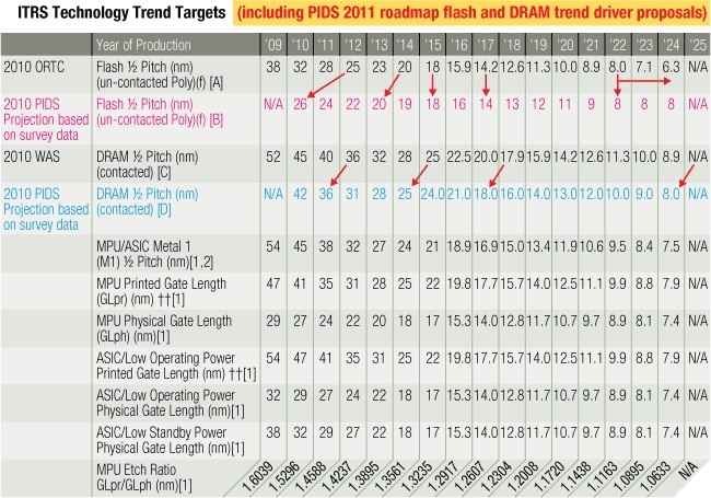
January 12, 2010 – The year 2010 is an even-numbered year, so the update to the International Technology Roadmap for Semiconductors (ITRS) generally undergoes few changes, saving the major changes for odd-numbered years. Nevertheless, substantial changes have occurred in 2010, including boosts in the timelines for NAND flash and DRAM device rollouts, backup plans for lithography forced by EUV delay, impending device and interconnect structural changes, and progress in 3D packaging.

The 2010 ITRS executive summary [PDF link] does an excellent job of highlighting the changes from 2010-2024 by chapter. Following is a much more abbreviated version of the top processing highlights.

Process integration, devices and structures

When the roadmap committee talks about low standby power (LSTP) and low operating power, they mean low. In 2010, in low-power logic LSTP, off-current Ioff is reduced from 50 pA/μm to 10 pA/μm to decrease the static power. The power supply voltage (Vdd) was lowered to similar voltages as those of high-performance technology to reduce dynamic power. As a result, operating speed will be reduced by 20%-57%, but will still maintain adequate levels for operation. In the low operating power regime, Vdd has likely been reduced, which reduced speed by 14%-34%, yet still meets necessary performance targets.

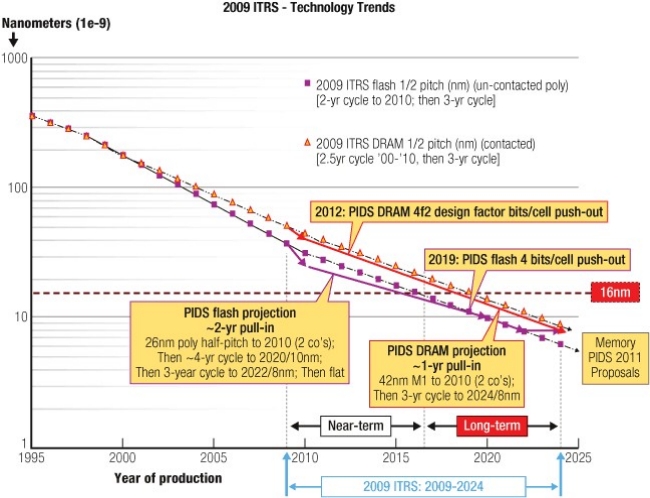
This year, half-pitch scaling was bumped up by one year from 2011 to 2010 for NAND flash and DRAM (Figures 1-2). DRAM adoption of FinFET structures is delayed by two years to 2012, vertical channels are expected in 2013, and the cell size change to 4F2 is delayed by two years. In flash memory, bit size accelerated by one year, while a transition to 3D stacking is delayed from 2014 to 2015. The change to 4 bits/cell, formerly expected in 2012, is delayed until 2019. The DRAM and flash timeline changes are included in the tables of the PIDS section of the ITRS only for 2010 but they will be proliferated to all sections and all tables in 2011.

Click to Enlarge


Click to Enlarge

Lithography

At 22 nm, flash memory manufacturers will continue to use 193nm immersion with double patterning (DP) as the lithography of choice, while awaiting a mature EUV infrastructure. The key challenges for EUV remain: ensuring defect-free masks, generating adequate source brightness, and fabricating optimal resist systems. Mask metrology for EUV is nonexistent. Looking forward, to surpass 16nm patterning capability, numerical aperture (NA) will have to be increased, introducing new challenges. Incidence angles may also need to be increased, requiring thinner absorbers and mitigation of flare.

Nevertheless, the roadmap architects point out that scanner throughput has been increased dramatically, making double patterning more production worthy. With mask systems, registration and overlay have also been improved to support double patterning.

The roadmap further indicates that while flash manufacturers are likely to stick with 193nm immersion, logic and DRAM manufacturers have time to consider the alternative NGL technologies, including extending 193nm immersion DP down to a k1 of 0.15 for 22nm half pitch, maskless lithography or imprint lithography. Each of these options faces substantial core and supporting infrastructure challenges.

Front-end processes

The most substantial changes in 2010 are driven by the etch challenges for advanced CMOS devices. As gate CDs shrink, microloading among various patterns becomes more critical, requiring improved OPC modeling accuracy. The dense vs. isolated pattern etch microloading effect is critical for SiGe recess etch because the SiGe/gate distance (critical for transistor performance) strongly depends on the degree of SiGe etch microloading.

For 3D interconnect technologies, gate CD control is critical because through-silicon vias (TSV) have been shown to cause high stress, caused by the thermal expansion coefficient mismatch between copper and silicon. As a result, manufacturers may set aside a transistor exclusion zone with TSVs, which is challenging due to high transistor density.

In 2011, the front-end processes group will look closely at the introduction of multigate FETs and III/V heterogeneous integration.

Interconnects

Most of the 2010 changes in interconnect technology reflect the introduction of 3D integration and emerging technologies that might succeed copper/low-k approaches. A significant challenge exists in sub-2nm copper barriers, as the industry considers hybrids of Ta/Ti(N) with a thin Ru top layer. PVD and ionized PVD techniques are currently pushed to the limit because ALD still fails to demonstrate manufacturability. Regarding low-k dielectrics, air gaps (vacuum, k = 1) moved from the emerging section to a manufacturing solution and are expected to be used for kbulk < 2.0 needs. Low-k solutions going forward will be less material based and more geometry based.

Delay and power requirements in the short-term will be best addressed by 3D chip stacking with high-density TSVs as well as multicore designs. The roadmap committee has mapped out TSV geometries for global and intermediate interconnect approaches (see tables below). Global interconnect (pitches to 4-16μm) solutions are in production but intermediate level solutions (1-4μm) require further work to allow use in production.

Global interconnect level 3D-SiC/3D-SoC Roadmap, updated
Global level, W2W, D2W, or D2D 3D-stacking
2009-2012
2013-2015
Minimum TSV diameter 4-8µm 2-4µm
Minimum TSV pitch 8-16µm 4-8µm
Minimum TSV depth 20-50µm 20-50µm
Maximum TSV aspect ratio 5:1-10:1 10:1-20:1
Bonding overlay accuracy 1.0-1.5µm 0.5-1.0µm
Minimum contact pitch (thermocompression) 10µm 5µm
Minimum contact pitch (solder µbump) 20µm 10µm
Number of tiers 2-3 2-4

Intermediate interconnect level 3D-SiC Roadmap, updated

Intermediate level, W2W 3D-stacking
2009-2012
2013-2015
Minimum TSV diameter 1-2µm 0.8-1.5µm
Minimum TSV pitch 2-4µm 1.6-3.0µm
Minimum TSV depth 6-10µm 6-10µm
Maximum TSV aspect ratio 5:1-10:1 10:1-20:1
Bonding overlay accuracy 1.0-1.5µm 0.5-1.0µm
Minimum contact pitch 2-3µm 2-3µm
Number of tiers 2-3 8-16 (DRAM)

Interestingly, an Emerging Interconnect Properties section of the ITRS is exploring first-principles of interconnect properties to determine if a combined first-level interconnect and next-generation (non-FET) switch would be most advantageous following exhaustion of the CMOS switch. Possibilities include a switch/interconnect based on carbon nanotubes or graphene.

Yield enhancement, test & packaging

In 2010, the Yield Enhancement technology working group embarked on a survey of fabs in the US, Japan, and Europe to gather defect density data for production processes and equipment. The information will be used to improve the ITRS Defect Budget and Yield Model.

One of the great testing challenges reflects the added complexity of ensuring the reliability and quality of stacked devices with TSVs. Cost containment requires creative solutions beyond testing connections and testing logic blocks and cores.

The roadmap also calls for better simulation and modeling tools for 3D packaging approaches to limit the high cost and time delay of fabricating multiple prototypes. The most difficult challenges in packaging are summarized in the table below. In 2011, readers can also look forward to expanded coverage of packaging automotive electronics, optical component packaging including optical fiber data paths, LED packaging, and photovoltaic packaging requirements.

Assembly and packaging
difficult challenges ≥16nm
Summary of issues
Impact of BEOL including Cu/low-k on packaging
  • Direct wire bond and bump to Cu or improved barrier systems bondable pads
  • Dicing for ultralow-k dielectric
  • Bump and underfill technology to assure ultralow-k/ air gap dielectric integrity
  • Improved fracture toughness of dielectrics
  • Interfacial adhesion
  • Reliability of first level interconnect (increasing with decreasing contact pitch)
  • Mechanisms to measure the critical properties (particularly for thin layers and interfaces)
Wafer-level packaging
  • Redistribution processing for pad pitch below 50µm
  • Thermal management (for high power devices used in automotive and other areas)
  • Wafer thinning and handling technologies
  • TCE mismatch compensation for large die
Coordinated design tools and simulators to address chip, package, and substrate co-design
  • Models for reliability prediction
  • Rapid-turnaround modeling and simulation
  • Integrated analysis tools for transient thermal analysis and integrated thermal mechanical analysis
  • Electrical (power disturbs, EMI, signal and power integrity associated with higher frequency/current
    and lower voltage switching)
  • System level co-design(cm to nm) is needed now (including mixed signal and simulation).
  • EDA for "native" area array is required to meet the Roadmap projections.
Embedded components
  • Low-cost embedded passives: R, L, C
  • Embedded active devices
  • Quality levels required not attainable on chip
  • Die size for high-C, low-L integrated circuit matching die size
  • Wafer-level embedded components
Thinned die packaging
  • Wafer/die handling for thin die (must address die warpage)
  • Reliability
  • Stress impact on device performance and
    assembly yield
  • Interconnect thickness and bonding for die stacking
  • Testability (ohmic contacts without damage)
Technology forecasts for 22nm
Addressing defectivity will require new surface-engineering processes at 22nm
RoHS, device shrinks will continue to drive packaging technology
Tooling and process technology vital for thin packages
More collaboration is needed to improve process integration
22nm brings maskmakers, end users closer
22nm: The era of wafer bonding
Failure analysis challenges at 22nm drive the need for turn-key failure analysis solutions
A materials evolution and revolution for 22nm devices
Enabling lithography for the 22nm node
Keys to CMP and cleans: Defect reduction and process customization
Gate structure/3D stacking "winners" will determine industry direction

This is an online exclusive essay in SST’s Forecast for 2011: Back to Reality series.

Paul Kirby, Senior Product Manager, FEI, Hillsboro, OR USA

Click to EnlargeJanuary 11, 2011Detailed analysis of structures on 22nm semiconductor devices is pushing the boundaries of conventional scanning electron microscope (SEM) technology.  Even though equipment manufacturers continue to enhance the resolution of SEM-based tools, more and more failure analysis (FA) work is being conducted on transmission or scanning transmission (S/TEM)-based systems. TEM-based techniques offer the imaging resolution and analytical capability to take the industry well beyond 22 or even 15nm. To accomplish this, however, requires very thin sections to isolate the structure of interest. These sub-20nm-thick sections must contain the region of interest and require the ability to stop the thinning process at exactly the right time to capture what is frequently a one-of-a-kind defect.

At the 22nm technology node, we are seeing a shift to complex 3D device structures, such as FinFETS, that give more efficient control of the switching process by wrapping the gate electrode around the switched channel. This type of design necessitates even more precise end-pointing and sample preparation. These 22nm structures give us an insight into future transistor designs, where simple, 2D SEM cross section or S/TEM projection may not be able to reveal all of the important detail. It is possible to envision a future where 3D analysis techniques, such as electron tomography and slice-and-view reconstruction, could play increasingly important roles.

These complex structures are incorporating new materials that pose sophisticated analytical challenges. The challenge is made more difficult by sample thinness, which reduces the interaction volume and the strength of the Xray signal typically used for analysis. Advanced detector designs that collect more of the available signal have yielded tremendous gains in analytical speed and precision. These new materials are also driving a move to lower accelerating voltages that reduce damage to the sample.

Finally, we are experiencing a convergence to 3D packaging that involves combining many high-value chips together with advanced interconnect technologies, such as through-silicon vias (TSVs). The cost of failure is magnified by the fact that a failure in any one chip scraps the whole stack of very expensive, perfectly good die. This packaging FA problem lies at the other end of the size scale from wafer-based FA, since the analysis requires the rapid removal of relatively large amounts of overlying material without destroying the information contained in the failure. Plasma-based ion sources promise very high beam currents for fast milling, while preserving sufficient small spot (low current) performance to provide good imaging.

The ultimate challenge is to provide solutions to these problems that still meet the budget constraints of device manufacturers. Since the instrumentation is inherently more expensive — TEMs for imaging and analysis, and DualBeam (FIB/SEM) systems for sample preparation — the best solution lies in higher throughput that amortizes the cost over more samples. Equally important is reducing time-to-data to facilitate faster corrective action. These considerations all argue against more complex instrumentation and in favor of dedicated turnkey solutions that are faster and easier to use. 

Subscribe to Solid State Technology/Advanced Packaging.

Follow Solid State Technology on Twitter.com via editors Pete Singer, twitter.com/PetesTweetsPW and Debra Vogler, twitter.com/dvogler_PV_semi.

Or join our Facebook group

This is an online exclusive essay in SST’s Forecast for 2011: Back to Reality series.

Arthur W. Zafiropoulo, Chairman & CEO, Ultratech, Inc., San Jose, CA USA

Click to EnlargeJanuary 11, 2011 — Historically, companies transitioned from the 45nm node and then slipped into the 40nm node. At 32nm, they shifted into 28nm, and for 22nm, they seem to be migrating into the 20nm node. As a result, I envision the device landscape as both 20 and 22nm. For the most part, metal gate structures will be more prevalent than silicon gate structures for the 20/22nm technology node. The most interesting question is whether it will be "metal gate first" or "metal gate last." IBM is leading the metal gate first method and Intel is pushing metal gate last. It will be interesting to see the benefits of each method and which one will produce the higher yield with lower device cost. There are pros and cons to each one of these major gate structures. Work is currently being done by other companies as well, but I would say that it’s at a stage where Intel seems to have the lead for 20/22nm structures.

There will be many challenges surrounding materials selection for 22nm, which will ultimately affect yield. Also, as we see the 20/22nm structures begin to be implemented, there will be a larger percentage of those wafers packaged using flip-chip bump. There is an increase in demand for bump in a larger percentage of wafers, as the industry shifts from wire bonding to bump packaging, primarily for smart phones and tablets. As we transition from laptops to tablets, and from on-board disk drives to cloud networking, these devices will drive the transition. Companies like Apple, producing microprocessors that deliver very rich quality from its devices at a much lower cost than other dedicated microprocessor companies, also disrupt status-quo in the semiconductor industry.

For junction formation and leakage, there is a growing set of problems caused by using older technologies. As we progress to smaller features, laser annealing plays a much more important role in the structure’s performance, significantly lowering leakage. There is greater potential for laser application than there was at the 28nm or 40nm nodes. In the next couple of years, I believe that through-silicon via (TSV) for 3D stacking will increase in usage for multiple stacked chips, which will reduce cost and increase performance for tablets, smart phones, and related devices. This change will make TSV 3D stacking a strategic weapon for many chip manufacturers.

With the many technology transitions that need to occur to move to the 20/22nm node, the gate-first/gate-last debate winner will set the direction for the rest of the industry. The transition to TSV 3D will ultimately decide the winner for the balance of this decade. For certain, change is on the horizon.