Category Archives: Wafer Level Packaging

January 17, 2011 — CEA-Leti is expanding its technology offering, ramping up one of Europe’s first 300mm lines dedicated to 3D-integration applications.

The new line, dedicated to R&D and prototyping, includes 3D-oriented lithography, deep etching, dielectric deposition, metallization, wet etching, and packaging tools that will be available for Leti’s customers and partners around the world.

By adding this technology to its existing 300mm CMOS R&D line, Leti now can offer heterogeneous integration technologies to customers on both 200 and 300mm wafers.

It will allow Leti to apply its 3D-integration generic processes on 300mm wafers. This 3D toolbox includes a large portfolio of through-silicon vias (TSV), and advanced capabilities in alignment, bonding, thinning, and interconnects in specific integration schemes for manufacturing optimized die stacks and building efficient advanced-systems solutions. This will be done in close collaboration with local design and characterization platforms.

"This extension offers important new capabilities to equipment manufacturers and other Leti partners," said Laurent Malier, CEO of Leti.

CEA is a French research and technology public organization, with activities in four main areas: energy, information technologies, healthcare technologies and defence and security. Within CEA, the Laboratory for Electronics & Information Technology (CEA-Leti) works with companies in order to increase their competitiveness through technological innovation and transfers. CEA-Leti is focused on micro and nanotechnologies and their applications, from wireless devices and systems, to biology and healthcare or photonics. Nanoelectronics and microsystems (MEMS) are at the core of its activities. For more information, visit www.leti.fr.

Subscribe to Solid State Technology/Advanced Packaging.

Follow Advanced Packaging on Twitter.com by clicking www.twitter.com/advpackaging. Or join our Facebook group

January 12, 2011 — JEDEC Solid State Technology Association, standards developer for the microelectronics industry, today announced that its JC-64.8 Subcommittee for Solid State Drives will target the development of standards for SSDs in applications beyond conventional disk drive form factors.

Building on JEDEC’s leadership in the development of standards for solid state drives and the success of recently published SSD standards JESD218 and JESD219, the interest in standardizing SSDs for non-traditional applications is being driven by rising demand for smaller consumer electronics devices. Interested companies are encouraged to contact the JEDEC office at 703-907-7560 or visit www.jedec.org to become involved with SSD standards development.

"Momentum for adoption of embedded SSDs continues to grow and with the right OEM support, Gartner believes that embedded SSDs could potentially out ship traditional SSD form factor usage in mobile PCs by 2013," according to Joseph Unsworth, research director at Gartner.

To answer the data storage market’s demand for faster, more energy efficient solutions in a smaller footprint, the use of SSDs in alternative form factors may provide an answer for product design engineers. SSDs in module and/or package form offer the ability to meet the demand for a smaller form factor, z-height advantages, as well as potential cost savings over traditional hard drive form factors. However, in order to fulfill this potential, widely adopted industry standards are seen as essential tools to reduce market confusion, facilitate broad adoption and alleviate product quality and reliability concerns.

"Deploying the first generation of SSDs in disk drive form factors leveraged the existing ecosystem and helped ensure supply chain flexibility," said Mian Quddus, JEDEC Board of Directors Chairman. He added, "But with tablet PCs and ultra-thin portable notebooks emerging in Client as well as high-density Enterprise systems, there is a growing demand for SSDs in smaller form factors and an urgent need for related industry standards. I strongly urge all interested companies to participate in the development of solid state drive standards within JEDEC."

JEDEC is the leading developer of standards for the microelectronics industry. Over 3,000 participants, appointed by nearly 300 companies, work together in 50 JEDEC committees to meet the needs of every segment of the industry, manufacturers and consumers. The publications and standards that they generate are accepted throughout the world. All JEDEC standards are available online, at no charge. For more information, visit www.jedec.org.

Subscribe to Solid State Technology/Advanced Packaging.

Follow Advanced Packaging on Twitter.com by clicking www.twitter.com/advpackaging. Or join our Facebook group

January 12, 2011 — Popular consumer products such as smartphones, tablet PCs, and LED televisions have created demand for a new breed of low-cost advanced packaging technologies. There are a few key attributes in the highest demand for devices targeting these applications: a reduced footprint and/or profile, high electrical performance, fine-pitch design, custom features, and a low cost.

As consumer applications evolve into smaller, feature-rich devices, the supply chain must respond to meet these low-footprint, high-density component packaging demands. Over the last several years, the quad flat package no leads (QFN) package has been the standard device due to the benefits it offers (small, light, better thermal, etc.). Devices are getting smaller and are proving to be a challenge to assemble with finer pitches and longer bond wires. The introduction of dual-row QFNs has helped to reduce the package size and improved manufacturability. But these multi-row QFNs present their own challenges including finding manufacturers that can produce good lead features and ensuring the capability of an SMT house to mount multi-row QFN with no lead standoff height. In some cases, they also affect singulation by requiring a dual-pass process.

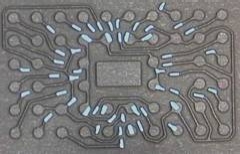
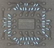
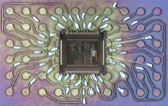
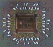
Newer technologies have taken the dual-row QFN a step further. The etched leadless package (ELP) offers flexibility with up to 3 rows with isolated pads, power and ground rings. This gives the device manufacturer options to optimize product performance. The triple-row capability provides an even smaller footprint having more I/Os. Another advantage of this package over standard QFNs is that the sawing process only cuts the mold compound, improving the cutting speed by >2× and extending saw blade life of the saw blade.

Click to Enlarge Click to Enlarge Click to Enlarge Click to Enlarge Click to Enlarge
Figure 1. Variations of the etched leadless package (ELP).

Another newer multi-row QFN-style package is QPL’s HDL technology. Unisem has collaborated with QPL to introduce the technology to their package portfolio in 2010 as their leadframe grid array (LFGA) package. The LFGA is similar to the ELP package — greater flexibility in a leadframe-based package — and allows for even greater customization to simplify the wire layout. The higher density routing also enables use of even more rows of leads to further reduce package size. Active leads can be placed underneath the die, attached by non-conductive epoxy or die attach film (DAF).

  52 lead – 4.5x7mm form factor   52 lead – 4×4.5mm form factor
Leadframe internal design Click to Enlarge   Click to Enlarge
Front of line (FOL) assembly wire bonded  Click to Enlarge    Click to Enlarge
End of line (EOL) assembly after etching  Click to Enlarge    Click to Enlarge
Final package solder finish Click to Enlarge   Click to Enlarge

Figure 2. Leadframe grid array package (LFGA).

For an even smaller package size, there has been strong surge in the demand of wafer level chip scale packaging (WLCSP). With features like its small footprint, thin profile, light weight, and cost competitiveness, it is a true chip-sized package where I/Os can be fully populated within the chip using a redistribution layer (RDL). Typical chips size range from about 1 × 1mm to 6 × 6mm with bump pitches of 0.4mm or larger. The WLCSP is utilized heavily in handheld products such as smartphones, tablet PCs, and digital still cameras.

Electrical performance continues to be a priority for packaging as well and is a requirement for most levels of devices in consumer electronics. The conventional wire bonded device has some limitations on when it comes to clock speed and cross-talk due to wire proximity. Using flip-chip technology improves the device response by >10% and at the same time gives better thermal performance 10~20% with the use of thermal bumps when attached to the thermal pad. Flip chip with Cu pillar bump technology can further help to improve the electrical performance. The WLCSP package technologies with direct ball drop on the pads or on redistributed pads will also have lower inductance when compared with standard wire bond.

Today’s complex devices also require fine-pitch design feature capabilities. Multi-row and fully populated QFN-style package offer design capabilities that in the past were limited to more expensive ball grid array (BGA) substrate-based packages. The previously mentioned packaging technology from QPL that Unisem has introduced as the LFGA is able to support 0.4mm pad pitch. Flip chip and WLCSP packages are also able to offer finer pitch features. Flip chip bumping technologies such as the Cu pillar bump can achieve a bump pitch of 120µm vs. electroplated solder bump (150µm) and conventional ball drop (400µm).

Custom packaging or even die-level features may also be required to meet today’s consumer electronic requirements. Multi-chip packages (MCMs), also known as system in package (SiP), integrate multiple chips and passive components within the package and help to reduce footprint, improving electrical performance and cost competitiveness. SiP is widely used in RF application products such as frontend power amplifier (PA) modules. Using an integrated passive device (IPD) to replace passive components in a SiP package is also gaining popularity. IPDs help to simplify the substrate and leadframe design for module packages, reducing the footprint and packaging lead time.

Conclusion

With all these needed features and advances in leadframe and flip-chip-based packaging solutions, the pressure is still on the assembly provider to offer all this at a competitive price. Leadframe-based packaging is generally more cost efficient than those that use substrates. QFN, multi-row QFN, ELP, LFGA, and other similar technologies have the ability to achieve higher I/Os and are very cost efficient. WLSCP packages using the ball drop process on 200 and 300mm wafer sizes is cost efficient because there are no direct packaging materials required and it simplifies the back-end assembly processes.

Other assembly process solutions that can help lower the assembly cost are Cu wire bonding, smaller wire diameter, lower-cost bill of materials (BOMs), post wire bond taping, and using a jig saw instead of tape saw for QFN. Pre-plated leadframes (PPF) can also lower the cost of the assembly processes.

Leadframe and flip-chip packaging technologies continue to evolve and help provide the semiconductor industry with package solutions that are both cost effective and able to take on the complexities of today’s and tomorrow’s consumer electronics market segment. Characteristics such as a reduced footprint and/or profile, electrical performance, fine pitch design, custom features and a low cost are now able to be achieved with technologies such as the ELP multi-row QFN package and with bumping technologies such as the fine pitch copper pillar bump. Device manufacturers no longer need to migrate to BGA-style packaging when requirements become demanding or complex.

Rico San Antonio of Unisem (Batam, Indonesia) co-authored this article with Chris Stai, Unisem (Sunnyvale, CA). Contact them at [email protected].

Subscribe to Solid State Technology/Advanced Packaging.

Follow Advanced Packaging on Twitter.com by clicking www.twitter.com/advpackaging. Or join our Facebook group

Technology forecasts for 22nm
Addressing defectivity will require new surface-engineering processes at 22nm
RoHS, device shrinks will continue to drive packaging technology
Tooling and process technology vital for thin packages
More collaboration is needed to improve process integration
22nm brings maskmakers, end users closer
22nm: The era of wafer bonding
Failure analysis challenges at 22nm drive the need for turn-key failure analysis solutions
A materials evolution and revolution for 22nm devices
Enabling lithography for the 22nm node
Keys to CMP and cleans: Defect reduction and process customization
Gate structure/3D stacking "winners" will determine industry direction

(This is an online exclusive essay in SST‘s Forecast for 2011: Back to Reality series.)

Dave Foggie, semicon & alternative applications manager, DEK, Weymouth UK

Click to EnlargeJanuary 11, 2011 – There appears to be one goal driving the market in both the wafer-level and substrate-level sectors: getting thin! This is no diet fad but a real challenge for manufacturers that is impacting the technology needed to compete. Lower Z-heights are a key target in wafer-level assembly. Thinner wafers — we see 75μm regularly and are expecting 50μm thicknesses any time soon — work with smaller ball diameters to reduce component profile height. Then there’s the increasing use of thinner coatings for die attach materials; we’re seeing these drop from typically 50μm to as thin as 25μm to give improved performance through better conductivity and shorter signal paths. Thinner and leaner are features of a growing array of emerging packaging technologies, such as fan-in and fan-out, where encapsulated die with multiple I/O offer huge net gains in functionality.

Overall, these low-profile form factors are great news for the miniaturization demanded by end-user electronic products. But they have an impact on wafer bumping and ball placement, which is where manufacturers will need to exercise caution in otherwise proven and dependable processes.

And what of substrate level? Here, getting thinner also seems to be the trend for packaging. Take thin core and coreless technologies for instance: essentially very thin and flexible substrates that present their own problems, such as warpage and dimple distortion. Imagine a conventional flip-chip assembly with passives, some silicon, and underside bumps; it will measure about 1mm thick. But these new package technologies are pushing that down to 0.2mm or less, which is desirable because again, being thin is great for miniaturization. One downside that presents a challenge for device handling and processing is the propensity for the thin structure to "dimple" as the underfill cures and distorts the thinned substrate material. That can make the device less than perfectly flat.

This technology isn’t mainstream yet, but experimentation and feasibility studies are well underway and it shows the path for the future. My 2011 forecast is that innovative tooling and process technology will become paramount in addressing thinned packaging and ramping up to volume, reliably.

(January 10, 2011 – BUSINESS WIRE) — China WLCSP Co. Ltd., provider of wafer level (WLP) miniaturization technologies for the electronics industry, confirmed its commitment to the US market with the opening of a new R&D center in Sunnyvale, CA.

The R&D center will support China WLCSP’s regional activities with OEMs and industry partners in the growing mobile handset market.

"The US is a strategic market, which experiencing solid growth in the high-end mobile device market," said Wang Wei, CEO of China WLCSP. "We have several important customers and partners in the US, where we plan to play a leading role over the next few years."

China WLCSP is a leading provider of wafer level miniaturization technologies and processes for the electronics industry. China WLCSP enables new levels of miniaturization and performance by applying its unique expertise in the electrical, thermal and mechanical properties of materials and interconnect. As a result, China WLCSP’s technologies are widely adopted in high-growth markets including consumer, computing, communications and medical. China WLCSP is headquartered in Suzhou, China. Learn more at www.wlcsp.com.

Subscribe to Solid State Technology/Advanced Packaging.

Follow Advanced Packaging on Twitter.com by clicking www.twitter.com/advpackaging. Or join our Facebook group

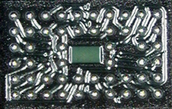
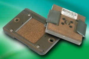
(January 7, 2011)Aries Electronics, an international manufacturer of standard, programmed and custom interconnection products, now offers machined high-frequency center probetest sockets to accommodate IC devices with a lead pitch of 0.30mm. With very low inductance and capacitance, the sockets suit various ball grid array (BGA), chip scale package (CSP), and micro land frame (MLF) packages.

Click to EnlargeReduced inductance, increased board density and finer-pitch array packages are made possible thanks to a four-point crown or sharp point gold-plated 0.30mm-pitch probe pin, spring and flanged bottom pin, which contacts the tail of the probe pin to shorten the signal path. A signal path of 0.077" (1.96mm) allows for minimal signal loss and higher bandwidth capacity with the new Aries’ machined high-frequency sockets.

The solderless pressure mount spring probes allow easy mounting of the socket to a test board and device solder ball or pad, while socket locating posts ensure accurate positioning of the socket to the board. The sockets are equipped with chip guides to allow exact device location and four-point edge male contacts for precise mating of the device. The socket’s small footprint ensures maximum use of the test board area for increased efficiency.

Spring loaded contacts, made of gold-plated beryllium copper, provide a high life cycle of up to 500,000 cycles. Socket body material is Torlon PAI and all hardware is stainless steel.

The socket’s contact forces are 15g per contact on a 0.30-0.35mm pitch, 16g per contact on a 0.40-0.45mm pitch and 25g per contact on a 0.50mm pitch or larger. Contact resistance is less than 40 milliohms. Probe self-inductance on the new socket is 0.51nH for large probes and 0.59nH for small probes.

The socket accepts solder ball sizes from 0.15 to 0.93mm. Insertion loss is 1dB to 10.1GHz for a larger probe at 0.80mm pitch and 1dB to 18.7GHz for a smaller probe at 0.50mm pitch.

For additional information, contact Aries Electronics Inc., http://www.arieselec.com

Subscribe to Solid State Technology/Advanced Packaging.

Follow Advanced Packaging on Twitter.com by clicking www.twitter.com/advpackaging. Or join our Facebook group

(January 4, 2011 – BUSINESS WIRE) — Nautic Partners LLC, a private equity firm with more than $2.5 billion of capital under management, has partnered with management to acquire Aavid Thermalloy LLC (Aavid). Aavid designs and manufactures high-performance thermal management products used in a wide range of electronics systems and energy supplies.

Aavid is headquartered in Concord, New Hampshire, and has global manufacturing facilities across China, North America, Europe, and India. Aavid’s products are used to dissipate heat and maintain optimal temperatures of high-performance electronic components used in servers, telecommunications equipment (base station controllers and devices that amplify signals at cell sites), alternative energy equipment (wind and solar power inverters), and industrial and medical electronics.

"Aavid is a market leader known for its high quality, engineered thermal management solutions," said Doug Hill, managing director of Nautic. "We believe there are considerable opportunities for growth, both within our existing customer base, geographies, and industry verticals, as well as through penetration of new end markets. Aavid will also continue to benefit from the trend of electronic systems becoming increasingly smaller and more powerful. This trend is resulting in higher temperatures in smaller spaces, leading to the need for more sophisticated thermal management solutions."

The Prudential Insurance Company of America provided financing for the transaction. Terms of the transaction were not disclosed.

Aavid is Nautic Partners’ eighth investment from its most recent fund, Nautic Partners VI, LP.

Nautic Partners is a middle-market private equity firm with over $2.5 billion of equity capital under management. Nautic targets equity investments of $25-$75 million, representing majority ownership in companies with proven business models, defensible market positions, and strong growth potential. Areas of focus include business services, manufacturing, healthcare, and communications. For more information, please visit www.nautic.com.

Aavid’s products are used in a wide variety of applications including enterprise systems, telecommunications equipment, power generation, industrial applications and a wide range of other uses. For more information, please visit www.aavid.com.

Subscribe to Solid State Technology/Advanced Packaging.

Follow Advanced Packaging on Twitter.com by clicking www.twitter.com/advpackaging. Or join our Facebook group

(January 4, 2010) — Michael A. Fury of Techcet blogs about the papers he saw at IEEE’s International Electron Device Meeting (IEDM 2010) in December. The final afternoon of IEDM (day 3, 12/08/10) continued with 4 parallel sessions and the halls and conference rooms were as crowded as they had been all week. I was compelled to spend nearly all of my time in the novel process technologies session.


Technical talks will be referenced by the assigned conference schedule number. Addi-tional information can be found online at 2010 IEDM Technical Program. All figures are reproduced with permission of IEDM.

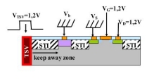
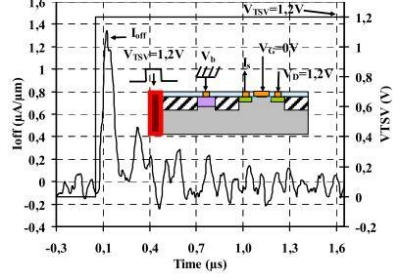
35.1: In order to quantify the impact of TSV structures on the electrical and mechanical properties of a 65nm CMOS device, H. Chaabouni of CEA LETI showed modeling and experimental work on 4µm Cu vias. Mechanical stress can affect mobility in FET devices, with PMOS being more sensitive than NMOS. This work found that a 1.7µm "keep away" zone around a TSV is needed for PMOS, none for NMOS. No effect was observed on ring oscillators as close as 5µm to the TSV. However, coupling between the TSV and FET was observed to induce a spike variation in the static NMOS drain current of up to 7µA/µm.

Click to Enlarge Click to Enlarge

Figure 1. Schematic of the 2D structure used to model the TSV coupling effect on NMOS transistors (TSV/NMOS distance: 2.5µm and 5µm). A square signal is applied on the TSV. The signal is rectified with buffers before the TSV. Paper 35.1.

Figure 2. Experimental measurement of the TSV dynamic coupling effect on the NMOS transistors leakage current (TSV/NMOS distance: 5µm). 1.4µA/µm spike variation observed. Paper 35.1.

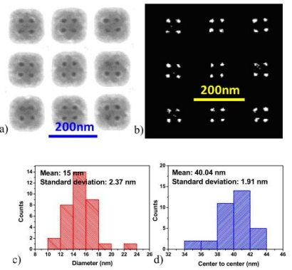
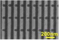
33.2: It’s amazing what’s being done with block copolymers these days. I never saw the point of them unless you were planning to make vast arrays of regularly spaced identical features. L.W. Chang at Stanford CIS showed that, with the proper placement of confinement channels and dummy structures as guide templates, you can induce directed self-assembly of reliable structures suitable for random logic designs. The work demonstrates the feasibility of processing features comparable to the natural polymer block, in this case 18nm diameters with 40nm spacing. Tweaking the template allows you to introduce additional features that would otherwise be considered outside the realm of the naturally occurring repeat pattern.

Click to Enlarge Click to Enlarge

Figure 1a) Square array of self-assembled holes in square wells with 135nm side length; b) shows the binary image of a) with 36 self-assembled holes. c) and d) show the distributions of the hole diameter with average value of 40nm extracted from b). Paper 33.2.

Figure 2. This SEM image demonstrates the formation of extra holes next to regularly packed self-assembled holes by introducing necking to the templates. Paper 33.2.

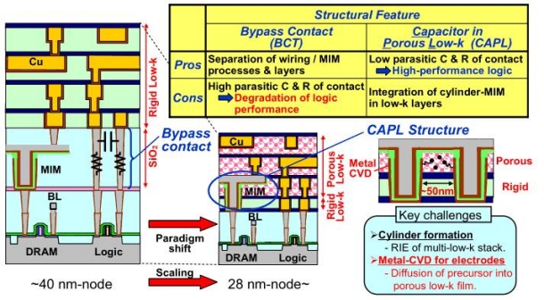
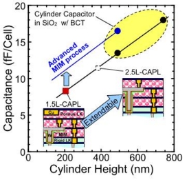
33.3: A cylindrical MIM capacitor for eDRAM in porous low-k, in which the devices are embedded in the Cu metallization layer, is proposed by K. Hijioka of Renesas Research. This naturally raises the issue of metal precursor diffusion into the low-k pores. A mo-lecular pore stack (MPS) SiCOH material with κ~2.5 and pore diameter ~0.4nm was found to be acceptable for blocking metal diffusion. TDDB of a 50nm MPS film was not degraded by CVD TiN when the MIM was integrated into 28nm eDRAM, and the MIM lifetime is projected to be >10 years. The structure is thought to be extendible to smaller nodes.

Click to Enlarge

Figure 1. Structural paradigm shift of eDRAM with cylinder-type MIM capacitors in scaled-down CMOS logics, which have porous low-k/Cu interconnects. Conventional MIM capacitors under M1-Cu need “bypass contacts (BCT),” of which the parasitic C and R increase with scaling to degrade the logic performance. Here, the researchers pro-pose a novel structure of capacitor in porous low-k film (CAPL). A key challenge is to control pore structure to keep away metal contamination in the porous low-k film during metal CVD for the MIM bottom electrode. Paper 33.3.

Click to Enlarge

Figure 2. Dependency of capacitance on cylinder height. Capacitance of CAPL was con-sistent to the trend of the conventional capacitor with BCT. The proposed CAPL is an extendable structure to boost the storage capacitance in the scaling eDRAM devices. Paper 33.3.

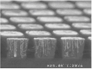
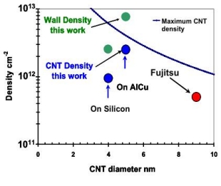
33.4: The integration of carbon nanotubes (CNT) into BEOL schemes is continuing apace. J. Dijon of CEA LITEN DTNM demonstrated CNT 1µm vias that are 10× more densely packed than previous work, and conductivity that is within engineering shouting distance of a Cu via baseline. Modeling indicates that 1013 CNT walls/cm2 are needed to meet Cu conductivity, and the present work achieved 2.5-8×10¹² walls/cm2. The 1nm diameter CNT are grown at 580°C in the via bottoms on exposed AlCu doped with Fe. These fluffy structures extend in length beyond the top of the via. They are densified by an IPA dip that shrinks the CNT ensemble to 64% of its unpacked diameter, then encapsulated with CVD Al2O3. The conductive tubes are re-exposed co-planar with the wafer surface by my old friend CMP, and top contacts are formed by liftoff. High resistivity of the via chains was attributed to contact resistance (whether top or bottom is unclear), but this seems to be a good start.

Click to Enlarge Click to Enlarge

Figure 1. 1000nm (1µm) via after encapsulating CNTs with Al2O3 deposited by ALD and CMP process. Paper 33.4.

Figure 2. State-of-the-art CNT density integrated in vias. CNT density by Fujitsu, on silicon by CEA. Green dots represent the integrated CNT wall density. Paper 33.4.

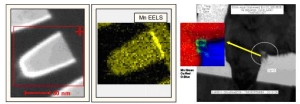
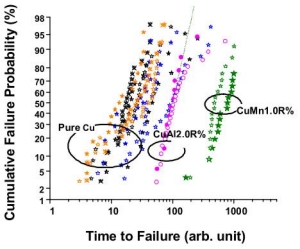
33.5: Manganese as a self-forming barrier film for Cu interconnects has been bandied about in several reincarnations since I first heard Shyam Murarka at RPI propose it in 1986. Among the current manifestations is work by T. Nogami at IBM Research, in which a CuMn seed layer with CVD Ta/TaN liner were integrated into a 32nm Cu BEOL. Data showed that CuMn had 2× the EM failure lifetime compared to CuAl with only 0.5× the at % doping level. The surface Mn is sacrificially oxidized, thus protecting the Cu surface. Optimization of the annealing process resulted in 20× more Mn at the surface while reducing the line resistance by 2×. Mn was concluded to have greater extendibility than Al for 22nm and beyond when considering future options that include Co, Ru and Ta in the barrier stack.

Click to Enlarge Click to Enlarge

Figure 1. EEDL maps of segregated Cu at the Cu top surface and the damaged liner location. Paper 33.5.

Figure 2. E-M comparison at 32nm node BEOL among pure-Cu, CuMn1.0R% and CuAl2.0R%. Paper 33.5.

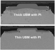
33.6: The convergence of shrinking dimensions, fragile low-k dielectrics, and the mandated replacement of PbSn solders have raised the bar for advanced flip chip interconnects. C.S. Chen of TSMC R&D presented a geometric design modification for 40 and 28nm nodes that was optimized concurrently with material modifications in the bump metallurgy, PI thickness opening, and Al pad size. A fine pitch (<150µm) Pb-free flip chip assembly solution for >400mm2 chips was shown to meet reliability specs.

Click to Enlarge Click to Enlarge

Figure 1. Under-bump metallization (UBM) scheme (thick vs. thin) plays an important role in post-thermal-cycling bump integrity. After TCB1000, thick UBM with polyimide (PI) shows serious bump fatigue while thin UBM with PI does not. Paper 33.6.

Figure 2. 3D plot on response surface of simultaneous optimization for 3 important parameters: bump size, polyimide via size, and aluminum pad size. Such a study avoids local optimization and parameters that interact with each other. Paper 33.6.

I was quite impressed that even for the last paper of the conference, the room was still respectably full. This is indeed a serious conference!


Michael A. Fury, Ph.D, is senior technology analyst at Techcet Group, LLC, P.O. Box 29, Del Mar, CA 92014; e-mail [email protected].

Also read: IEDM Reflections

Subscribe to Solid State Technology/Advanced Packaging.


Follow Solid State Technology on Twitter.com via editors Pete Singer, twitter.com/PetesTweetsPW and Debra Vogler, twitter.com/dvogler_PV_semi.

Or join our Facebook group
(January 4, 2011 – PRNewswire via COMTEX) — Integrated Silicon Solution Inc. (Nasdaq: ISSI) completed the spin-off of its subsidiary, Giantec Semiconductor Inc., which focuses on the ASSP business that includes EEPROM and SmartCard products.

As part of the spin-off process, Giantec received an additional direct investment of $3.75 million from Shanghai Pudong Science and Technology Co., Ltd and $250,000 from Super Solution Limited, resulting in ISSI’s ownership percentage now being less than 50 percent. As such, the revenue and operating results of Giantec will only be included in ISSI’s consolidated financial statements through December 30, 2010, the date the new investment transaction closed. Thereafter, ISSI’s operating results will reflect its proportional share of Giantec’s net income or loss, and ISSI’s balance sheet will not include any of Giantec’s assets or liabilities. Giantec recorded $6.0 million of revenue in the quarter ended September 30, 2010.

"We are pleased that Giantec has received new investment from Shanghai Pudong Science and Technology and Super Solution Limited. Their investment provides Giantec with additional capital for growth, and we believe further enhances Giantec’s position in the Chinese market as a stand-alone company," said Scott Howarth, ISSI’s President and CEO. "This transaction also enables ISSI to focus our efforts and resources on further growing our business and penetrating our target markets."

ISSI is a fabless semiconductor company that designs and markets high-performance integrated circuits (ICs) for digital consumer electronics, networking, mobile communications, automotive electronics, and industrial sectors. Visit http://www.issi.com

Also read: Reducing Flip Chip BGA Open and Short Fail Rate, by ISSI

Subscribe to Solid State Technology/Advanced Packaging.


Follow Solid State Technology on Twitter.com via editors Pete Singer, twitter.com/PetesTweetsPW and Debra Vogler, twitter.com/dvogler_PV_semi.

Or join our Facebook group
(January 3, 2011 – PR Newswire) — CoorsTek Inc., technical ceramics manufacturer, completed its purchase of the advanced ceramics business of Saint-Gobain. CoorsTek adds manufacturing facilities and product lines such as silicon carbide for semiconductors.

CoorsTek now owns and operates 44 facilities on four continents. Specifically, CoorsTek adds six manufacturing facilities in Europe, four in the United States, one each in Canada, Mexico, and Brazil, and distribution and sales offices in Japan, China, Taiwan, and Singapore.

Product lines and materials added include: silicon carbide for use in semiconductor processing equipment; proprietary silicon carbide ceramic blends used in hot surface ignition systems; silicon nitride used to make extremely durable bearings; mullite used in molten metal filtration; steatite for electrical appliance markets; and specialty ceramics for custom, critical-duty applications.

CoorsTek is familiar with acquisitions, buying Gaiser Tool in 2007.

Celebrating its 100th year in business, CoorsTek is a technical ceramics manufacturer supplying critical components and complete assemblies for defense, medical, automotive, semiconductor, aerospace, electronic, power generation, telecommunication, and other high-technology applications. For more detailed information about the expanded product offerings post-buy, visit http://www.coorstek.com/sgb-acquisition.asp.

Saint-Gobain designs, manufactures and distributes building materials. For more information, please visit http://www.saint-gobain.com.

Copyright 2011 PR Newswire Association LLC All Rights Reserved

Subscribe to Solid State Technology/Advanced Packaging.

Follow Advanced Packaging on Twitter.com by clicking www.twitter.com/advpackaging. Or join our Facebook group