Category Archives: 3D Integration

June 6, 2011 – Imec and Cadence say they have developed a design-for-test and automatic test pattern generation technology to more easily test 3D stacked ICs with through-silicon via (TSV) functionality, adding only "negligible" area costs.

The 3D DFT architecture, extended from imec’s research program into TSV-based 3D IC design and technology, is based on the concept of die-level test wrappers to enable testing of chips with TSVs at all three stages of stacking — before ("pre-bond"), during ("mid-bond"), and after ("post-bond") — as well as after packaging.

The design flow automation for adding 3D-enhanced IEEE 1500-based die wrappers to existing chip designs was created by enhancing existing IEEE 1500 wrapper insertion support in Cadence’s Encounter RTL Compiler synthesis product. Initial results on customer design show implementation of 3D DFT structures with "negligible area costs" of ~0.2%, far less than had been speculated.

"Using 3D-IC and TSV technology, electronics companies look forward to creating a new generation of super chips," said Erik Jan Marinissen, principal scientist at imec, in a statement. "The imec-Cadence offering inserts DFT structures with minimal area overhead, and the ATPG method helps drive towards zero manufacturing defects on the TSVs. This unique offering reduces risk and promotes cost-effective fabrication of these chips."

June 1, 2011 – Updating on plans announced a year ago, Elpida and Powertech Technology and UMC have finalized their partnership to develop a "one-chip" 3D IC solution incorporating logic+DRAM interface design, through-silicon via (TSV) formation, wafer thinning, testing, and chip stacking assembly.

The joint development work at Elpida’s plant in Hiroshima, Japan, which targets advanced processes including 28nm, leverages each company’s specific know-how: Elpida’s DRAM (it’s used TSVs in DRAMs since 2009), UMC’s logic (particularly SoC), and PTI’s assembly (thinned wafers, die-attach, and systems-in-package). Industry reports from last summer had indeed projected a mid-2011 sampling on UMC’s 28nm process, with a volume ramp in mid-2012.

Closely integrating all those components and processes is expected to deliver the performance required by ongoing convergence of communication, consumer, and computing applications in mobile and handheld electronics, the companies say.


Executive Overview

Performance requirements such as increased bandwidth, reduced latency, and lower power are driving the adoption of 3D-IC designs. What technology will be needed to make 3D-ICs a market reality at 45nm and below? While there are several options in development and production, one that is being touted as a way to build 3D-like structures relatively quickly is the use of silicon interposers—a double-sided die with no active devices that is used to connect one active die to another. Silicon interposers are being used to stack chips side-by-side, allowing designers to put dies next to each other in a high-bandwidth, low-latency configuration. However, while they provide a way to realize many of the benefits of 3D-ICs with fewer design and production issues, silicon interposers still pose new challenges for designers and manufacturers alike.

Matthew Hogan, Mentor Graphics, Wilsonville, OR USA

A complete 3D-IC implementation is usually envisioned as a stack of active chips using through-silicon vias (TSV) to connect through each chip down to a package substrate. TSV designs represent a convergence of the SoC and SiP disciplines, providing designers the means to significantly increase the bandwidth between the logic chip and the memory (especially with wide memory interfaces) that can’t be achieved with bond wires, as well as the ability to mix and match dies that not only use different process nodes, but also different manufacturing technologies (SiGe, SOI, CMOS low voltage, CMOS high voltage, BiPolar, GaAs, etc.). The ability to combine different dies in a single stack, while not new, allows design houses to focus on their core design strengths, and acquire needed functionality (e.g., memory, RF transmitter) from specialist companies who can provide high-quality, proven die. What is new with 3D-ICs is the ability to place those connections in a dense array, without the strict perimeter constraints imposed by an equivalent wire-bonded design.
Click to Enlarge

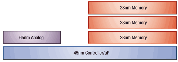
Figure 1. Stacked chip design.

Utilizing stacked chips, particularly in memory-intensive designs, allows designers to stay at today’s "reasonable" process nodes for each die and derive the benefit of proven volume manufacturing processes. For example, if designers want to add memory to an existing design, they can simply add memory on a TSV die, and go "up" (Fig. 1). This flexibility lets engineers easily create variations of a design just by adding more memory to the stack.

However, TSVs used in active silicon have their own performance and production issues, making full 3D-IC implementations problematic. Of particular concern for a full 3D-IC stack is the issue of thermal reliability, particularly in high power configurations. Stacked dies can’t easily dissipate heat in the same way a single die does (through the use of a heat sink covering the largest surface area), which results in performance degradation and/or early failure. Minimizing heat production and/or controlling and dissipating heat effectively and economically is a challenging design and implementation issue for these structures.

In an active die, the physical size of a TSV (15-30µm diameter) is very large compared to the transistors that surround it (20-40nm). This significant difference in scale has a profound effect on routing, cell placement, and transistor stress (to name a few), all of which become a challenge when designing with TSVs in an active die. While creating space around the TSV can help alleviate these factors, that technique must be balanced against the resultant reduction in area available for transistors that provide the functionality of the device.

Alternative 3D technology

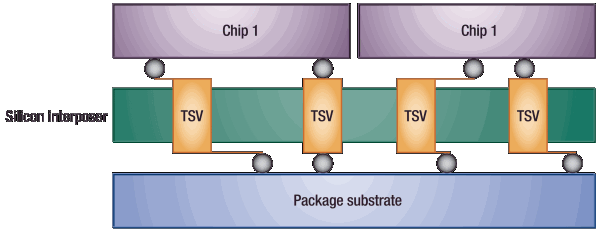
An alternative approach to a full 3D-IC stack is to place active dies on a passive silicon interposer, which in turn is placed on the package substrate. Silicon interposers with TSVs offer a way for designers to achieve the benefits of chip-scale connected configurations, without having to confront the issues currently presented by a full 3D-IC implementation through active silicon. The use of a silicon interposer is often referred to as a 2.5D-IC.

By using a silicon interposer, designers keep the circuitry of each active chip internal to the device package, reducing the need for HBM (human body model) electrostatic discharge (ESD) protection circuits and guard rings. Using a silicon interposer also makes it easier to "mix and match" active chips by using the interposer as a "rewiring loom" to connect chips without the need to specifically design them for interface compatibility (Fig. 2).
Click to Enlarge

Figure 2. Using a silicon interposer allows for signal remapping from one active chip to another without requiring customized designs.

Silicon interposers are seen by some as a pragmatic building block in the evolution of 3D-IC technology. They are often used in high performance applications with single stacked devices (flip-chips) that allow for generous thermal dissipation using traditional techniques. Silicon interposers also provide a variety of additional benefits:

  • Dies are created by a single source (no outsourcing to third party suppliers)
  • Reduced ESD protection requirements for die-to-die connections through the interposer
  • Drivers (transistors) need not be as large, because they’re not driving wirebonds to on-board (PCB) connections
  • Heat buildup experienced in full 3D-IC designs may be avoided/minimized
  • Process requalification is eliminated, because each die can be manufactured at a proven node without a TSV through the active silicon (for single stack configurations)

Looking ahead

For optimal package-aware chip design, questions must be asked and decisions made early in the design process. Is the connectivity created with the silicon interposer assembly the connectivity that you want? More specifically, when you have multiple dies sitting on top of the silicon interposer, how do they interact with each other? Will your power delivery match your performance requirements? Without the "right" answers to these questions, designers may not be getting the benefits this technology is intended to provide.

Standards are beginning to emerge for interposer size and pitch needed to meet performance standards. JEDEC recently announced that several of their standards committees are focusing on the development of 3D standards for stacked devices and mixed technology ICs [1]. The 3D-IC Alliance has released the Intimate Memory Interconnect Standard (IMIS) to standardize vertical interconnect requirements [2]. However, standards development may be hindered by some who perceive the interoperability of required technologies as a competitive disadvantage. Independent development and potentially conflicting solutions are always a risk.

Chip designers also need to decide how best to connect third party die that will require additional information. For example, to effectively use bare memory die, the micro-bump pad sites for each of the dies need to be aligned so the connectivity from one die can be traced through the passive silicon interposer and connect to the correct location on the other active die. Without knowledge of the physical interface, designers cannot effectively design the silicon interposer to connect with the die. However, information such as pad interfaces of an independent die is typically not a standard deliverable used in the design of another chip. Determining what information is needed and developing standardized methods of providing it will be needed.

From a design and verification standpoint, however, the good news is that extensive retooling is not needed. Many existing tools can be incrementally extended to handle 3D-IC design [3]. Incremental capabilities will be added to existing tools for coarse grain partitioning of designs, such as that of memory on logic, or other cells from one die to another. Fine grain partitioning, where the logic of a cell is partitioned over multiple dies, is probably only valid for very specific architectures at this time. The primary limiting factor is the manufacturing capability of the foundries. With a TSV being such a large structure compared to the transistors and other vias in the circuit, it remains a very deliberately placed object. When a TSV is small enough, with fine enough placement pitch to become a ubiquitous circuit element, then fine grain partitioning becomes significantly more viable.

Conclusion

3D-ICs are moving from theory (and a decade of hype) into reality. While challenges remain, there is little disagreement that 3D-ICs provide solutions to performance issues being encountered at the most advanced nodes. Silicon interposers were once viewed as an "interim" technology to help designers realize many of the benefits of 3D architecture, while delaying the most difficult production issues associated with TSVs. They now seem set to stay as a valid alternative implementation to full 3D-IC designs, at least for some market segments, and will become an integral part of future design architectures for others.

References

1. "JEDEC Announces Broad Spectrum of 3D-IC Standards Development," March 17, 2011; http://www.jedec.org/news/pressreleases/jedec-announces-broad-spectrum-3d-ic-standards-development

2. "First Standard For 3D Chips," July, 2008; http://www.3d-ic.org/documents/IMIS_Press_Release.pdf

3 M. Hogan, D. Petranovic, "Robust Verification of 3D-ICs: Pros, Cons and Recommendations," 3D System Integration, 2009. 3DIC 2009. IEEE Inter. Conf., vol., no., pp.1-6, 28-30 Sept. 2009doi: 10.1109/3DIC.2009.5306522
URL: http://ieeexplore.ieee.org/stamp/stamp.jsp?tp=&arnumber=5306522&isnumber=5306519

Biography

Matthew Hogan received his BEng from the Royal Melbourne Institute of Technology and an MBA from Marylhurst U. and is a Calibre Marketing Engineer for Mentor Graphics, 8005 SW Boeckman Rd, Wilsonville, Oregon 97070; ph.: 503-685-7065; email [email protected].

More Solid State Technology Current Issue Articles
More Solid State Technology Archives Issue Articles

May 31, 2011 – STATS ChipPAC says it has widened its range of packaging configurations for its fan-out wafer-level packaging technology. Integrating through-silicon via (TSV) with integrated passive devices (IPD), on the company’s embedded wafer-level ball grid array (eWLB) platform, addresses complex designs, shrinking lithography nodes, and increased performance demands for mobile and consumer applications, according to the company.

Interconnecting through the silicon wafer surface (instead of around via wires) better utilizes space efficiency, improves formfactor, and improves electrical performance. Use of TSVs is particularly beneficial with passive devices, which take up a lot of space (up to 60%-70%) in a subsystem or SiP package.

Integrating the eWLB, TSV, and IPD technologies, "opens up a wide range of possible design configurations for SiP and 3D packaging at the silicon level," said Han Byung Joon, EVP/CTO of STATS ChipPAC, in a statement. "This is an effective approach to system partitioning which offers our customers an overall better system performance."

The company’s expanded range of package architectures includes single die, multi-die, ultrathin, system-in-package (SiP) and 3D packaging, with what the company calls "superior electrical and thermal operating characteristics."

Learn more about STATS ChipPAC at www.statschippac.com

Georgia Tech researchers have promoted an "all-silicon" packaging concept for several years, calling for integration of wafer-level and 3D stacking technologies to bring tighter node silicon, vertical die integration, and embedded passives together. Read about the idea in 3D Technology and Beyond: 3D All Silicon System Module by Ritwik Chatterjee, Ph.D., and Rao R. Tummala, Ph.D, Packaging Research Center – Georgia Institute of Technology

May 26, 2011 — Camtek Ltd. (NASDAQ and TASE: CAMT) received repeat automatic optical inspection (AOI) orders from an Asia-based foundry doing advanced micro bump inspection and metrology.

Systems should be installed during Q2 and Q3 2011.

3D IC technology is trending to advanced micro bumps (>10mm), and may reach up to 1 million bumps per die. Microbumps allow increased device interconnects on a small package footprint. Challenges arise in measuring such small bumps, including efficiently handling huge amounts of data, said Roy Porat, Camtek’s CEO, who expects that this customer will order more in the future. Camtek’s AOI systems combine high performance 2D and 3D metrology and inspection on one platform.

Camtek Ltd’s automated tools enable inspection of semiconductors and printed circuit boards (PCB) & IC substrates, using intelligent imaging, image processing, ion milling and digital material deposition. Learn more at www.camtek.co.il.

Subscribe to Solid State Technology/Advanced Packaging.

Follow Advanced Packaging on Twitter.com by clicking www.twitter.com/advpackaging. Or join our Facebook group

May 26, 2011 — Ivo Bolsens, Xilinx, compares crossover cars — sports car performance with station wagon utility — to semiconductor ASICs (high-performance) and FPGAs (flexible, easy to use, less NRE). The semiconductor industry needs a programmable platform that has ASICs’ capabilities.

Bolsens continues, "An ASIC has typically a large non-recurrent engineering [NRE] cost," saying that 28nm chips need almost one hundred million dollars invested, and then must turn a profit. FPGAs are more expensive on a component-by-component basis, but have lower NRE. Crossover SoCs should bridge the gap between ASICs and FPGAs.

Bolsens finishes the interview with a focus on 28nm 3D chip architecture — particularly the confusion around supply chain handoffs. "There has to be a lot more agreement on roadmaps and standards so that all the players…have a good understanding of where investments should go." Right now, there are "a lot of opinions."

Bolsens knows what he’s talking about. In late 2010, Xilinx introduced 28nm 7 series FPGAs using 3D packaging technologies. They dealt with the turbulence of the young 3D packaging supply chain and process flows firsthand.

Research consortia can play a role in advancing 3D packaging, as can EDA providers, Bolsens asserts.

More from the ConFab:

May 25, 2011 — imec’s 3D integration industrial affiliation program (IIAP) partnered with Atrenta Inc., SoC realization products provider to semiconductor and electronic systems industries, to developed an advanced planning and partitioning design flow for heterogeneous 3D stacked ICs.

Cost-effective, rapidly ramping 3D ICs require robust, accurate partitioning and early prototyping. The flow imec and Atrenta are working on aims to minimize design iteration rounds. They demonstrated their first EDA tool flow for 3D design at DAC 2010. 3D stacked ICs reduce package footprint, and offer shorter and faster interconnects, possibly at lower costs. Stacked IC designs can be modular, and reused over various systems. The technology best suits mobile and high-performance applications, stacked DRAM, imagers, and solid-state drives.

The number of potential processes to resolve a given system design problem (e.g., front to front, front to back, silicon interposer, technology choice for slices, via configurations, partitioning, etc.) is huge. Creating multiple full design solutions for comparison is prohibitively expensive and time-consuming. Robust, accurate partitioning and prototyping early in the design process, well before detailed implementation begins, will avoid much of this trouble.

Other 3D design challenges include thermal profiles (heat dissipation) and mechanical stresses from assembly configurations. Imec has developed compact thermal and mechanical models for rapid generation of heat dissipation and mechanical stress maps and has validated them using real 3D DRAM-on-logic packaged devices. Atrenta’s SpyGlass Physical 3D prototyping tool creates design "floor plans," which can be combined with the stress models developed by imec, to compare options in different scenarios before full design implementation.

Imec and Atrenta will be demonstrating this flow at the Design Automation Conference (DAC) in San Diego, CA, June 6-8, 2011, in the Atrenta booth (1643). See design partitioning across a 3D stack with routing congestion analysis, through silicon via (TSV) placement and backside redistribution layer (RDL) routing support. The demo will also include a display of thermal profiles on the 3D "floor plan." For more information about Atrenta’s demonstrations at DAC visit: http://www.atrenta.com/DAC2011/sessions_short.html

Imec performs world-leading research in nanoelectronics. Further information on imec can be found at www.imec.be.

Atrenta provides SoC Realization solutions for the semiconductor and electronic systems industries. Learn more at www.atrenta.com

Subscribe to Solid State Technology/Advanced Packaging.

Follow Advanced Packaging on Twitter.com by clicking www.twitter.com/advpackaging. Or join our Facebook group

by Jan Provoost, science editor, imec

May 25, 2011 – At the Imec Technology Forum (ITF, May 25-26 in Brussels), Pol Marchal introduced his talk on 3D chip technology by recalling some of the powerful trends in the semiconductor market. Each trend points to the next wave of applications using 3D chips with tightly integrated sensors.

One trend predicts that electronic devices will become smaller by a factor of 10 in the coming years. At the same time, new applications will require a bandwidth between memory and processor that can only be delivered by a tighter, on-chip integration of memory and processor cores.

A second trend is that applications will be integrated with forever more sensors. Think of the image sensors or movement sensors that come with nearly every phone nowadays. According to Marchal, smell will be next, calling for the integration of electronic noses, sensors that recognize hundreds of different vapors. To integrate these sensors, a tight 3D integration brings advantages: a smaller form factor, high IO density, reduced power consumption through much shorter connections with less parasity. In short, no technology compromises.

Imec is one of the research centers where 3D integration was pioneered. The technology flavor developed was 3D-SIC (3D stacked ICs), where dies are interconnected through the silicon with so-called TSVs (through-silicon vias). 3D SIC technology has now matured to a level where you will see products coming out of the fabs in the coming years.

But despite a maturing technology, the challenges to design and fabricate 3D SICs are still considerable. Marchal outlined how imec has recently build a first heterogeneous 3D design, a DRAM-on-logic test vehicle, with the goal to resolve 3D-related processing challenges, perform a first assessment of the compatibility of 3D & DRAM technology, "pipe-clean" the supply chain, and set up design rules for 3D.

According to Paul Marchal, the design and integration of sensor applications can benefit from a strong collaboration between the various supply chain partners — if it is focused on an attractive system roadmap for everyone involved.

Click to Enlarge
Imec logic IC stacked on commercial DRAM,
connected with TSVs and microbumps.


By Debra Vogler, senior technical editor

May 23, 2011 — SEMI’s been impressed with the ability of the industry to rebound and recover from the impact of the March 11 Japanese earthquake, noted Tom Morrow, EVP, Emerging Markets Group/Chief Marketing Officer, in an interview at ConFab 2011 (May 15-18, Las Vegas, NV). "By and large, the industry is responding," said Morrow.

Listen to Morrow’s talk:

  • Format: mp3
  • Length: 4:13
  • Size: 3.87 MB
  • Date: 05/23/11


Emerging markets — another major ConFab topic — are important for SEMI members, noted Morrow, and last year, the trade organization created a business unit just for these sectors. In particular, the LED industry is booming with long-term growth. "Many of the suppliers who support that industry are semiconductor suppliers as well," explained Morrow. "They see many of the same needs, some of the same processes and need for standards and industry collaboration that the semiconductor industry has developed to a very high degree." This collaboration will be necessary for the LED industry to reduce costs and accelerate the market.

Morrow noted that the trade organization’s standards program has resulted in a very robust 3D IC standards foundation in place for the manufacturing issues that need to be addressed to enable 3D architectures to prosper efficiently and effectively. “If we go into every system becoming a unique requirement, there will be delays to development of that industry,” said Morrow. SEMI has also supported 450mm standards as well as LED standards, which eliminate the kind of expensive differentiation that doesn’t add any value. “We can focus on innovation, which has always been the mechanism for new markets to be developed.”

More from The ConFab:

Subscribe to Solid State Technology/Advanced Packaging.

Follow Solid State Technology on Twitter.com via editors Pete Singer, twitter.com/PetesTweetsPW and Debra Vogler, twitter.com/dvogler_PV_semi.

Or join our Facebook group

May 23, 2011 — Amkor Technology, Inc. (NASDAQ:AMKR) completed its previously announced offering of $400 million aggregate principal amount of its 6.625% Senior Notes due 2021. The proceeds from the offering will be used to fund the company’s tender offer for the approximately $264.3 million aggregate principal amount of its outstanding 9.25% Senior Notes due 2016, for general corporate purposes, including the redemption of any 2016 Notes not tendered in the tender offer and the refinancing of the company’s 2.50% Convertible Senior Subordinated Notes due May 2011, and to pay related fees and expenses.

This announcement does not constitute an offer to sell or a solicitation of an offer to buy any of the notes, nor shall there be any offer, solicitation or sale in any state or jurisdiction in which such an offer, solicitation or sale would be unlawful.

The notes have not been registered under the Securities Act of 1933, as amended, or any state securities laws and may not be offered or sold in the United States absent registration or an applicable exemption from such registration requirements.

Also read: Lee Smith, Amkor, on the 3 generations of 3D packaging

Amkor is a leading provider of semiconductor assembly and test services to semiconductor companies and electronics OEMs. Learn more at www.amkor.com.

Subscribe to Solid State Technology/Advanced Packaging.

Follow Advanced Packaging on Twitter.com by clicking www.twitter.com/advpackaging. Or join our Facebook group