Category Archives: Materials and Equipment

(July 6, 2010) — Surrey NanoSystems launched an automated, versatile growth platform, NanoGrowth-Catalyst. Incorporating nine advanced nanomaterial processing techniques, the platform can synthesize a variety of nanomaterials including graphene, nanowires, and carbon nanotubes.

Click to Enlarge

Application versatility is enhanced by a multi-chamber design that ensures the purest processing conditions by continuously maintaining the substrate under vacuum from deposition of catalysts to growth of nanomaterials. This end-to-end vacuum processing is critical for the precursors and catalysts used for nanomaterials, which are easily contaminated by exposure to atmosphere.

Click to Enlarge

Surrey NanoSystems previously introduced a platform combining CVD and plasma-enhanced CVD nanomaterial growth techniques, says Ben Jensen of Surrey NanoSystems. "This new platform takes processing flexibility much farther. It offers the means to support and speed research across the spectrum of nanomaterials, combined with automated handling and control to help developers turn material growth ideas into practical and repeatable production processes."

Click to Enlarge

NanoGrowth-Catalyst will replace multiple pieces of equipment with a single automated system. The processing techniques supported by the new platform are low-pressure chemical vapor deposition (LPCVD) and plasma-enhanced CVD (PECVD), sputtering, sputter etching and ashing, delivery of solid- or liquid-phase catalysts/precursors, creation of controlled-density nanoparticle catalysts at room temperature, thermal annealing, rapid thermal processing (RTP), and a unique form of rapid thermal growth (RTG) that prevents agglomeration of catalyst particles.

The platform also supports broadband substrate degassing to remove surface contaminants before processing, helping to ensure the optimum adhesion of catalysts and films. An inductively coupled plasma source can additionally be fitted as an option at purchase or during the platform’s lifecycle, to optimize the generation of sensitive materials employed in growth processes.

A graphical user interface (GUI) controls the processing parameters and steps. With its range of techniques users can employ NanoGrowth-Catalyst for creating or delivering growth catalysts and precursors (the sputtering platform’s dual magnetrons also support co-deposition), depositing nanoparticles at room temperature, catalyst or material activation, growing materials, etching, and deposition of active or passive barrier films.

The system has three chambers: a load/lock chamber and two reaction chambers, plus an automatic transport system for moving wafers/substrates. End-to-end atmosphere-free processing ensures the highest purity conditions to minimize contamination and oxidation and ensure consistent and repeatable results. NanoGrowth-Catalyst occupies a cleanroom footprint of 1 × 2 m.

The specification for this platform came partly from requests by users of Surrey NanoSystems’ single reaction chamber NanoGrowth 1000n, and from researchers at Surrey NanoSystems and its research partner, the Advanced Technology Institute at the University of Surrey.

Surrey NanoSystems has received advance orders for the new NanoGrowth-Catalyst, and is currently manufacturing an initial batch of three systems.

In addition to making growth platforms, Surrey NanoSystems is engaged in developing nanoelectronics materials and processes to support the continued scaling of semiconductor devices. The company has already made significant advances in developing practical techniques for fabricating interconnection vias and low-k dielectrics for inter-layer insulation. For more information, visit http://www.surreynanosystems.com. Surrey NanoSystems is represented in the USA by Axiom Resources Technologies, www.axrtech.com

(July 2, 2010) — Interplex NAS, supplier of precision components and assemblies and a division of Interplex Industries, Inc., added to its line of solder and flux-bearing lead products. The new surface mount pin, a short-current path lead, offers advantages in the circuit assembly process.

The lead (Product Code 34AC) possesses a pitch of 2.54 mm with a low-profile design for surface mount applications in restricted places. Its short current path is ideal for high-frequency electronic applications. Manufactured from a nickel-iron (NiFe) alloy and post-plated with a 60/40 tin/lead (SnPb) bright finish over nickel, the component can be configured for dual inline and quad packages

Interplex NAS’s patented solder and flux bearing leads are designed for assembling reliable hybrid and PCB circuits. Interplex NAS leads contain a flux-cored solder preform that creates consistent high-quality solder joints, quickly and economically. They enable one-step assembly and reflow operation that consistently produces 100% solderability, thereby eliminating the need for costly inspection and rework. Customers report that Interplex NAS solder and flux leads allow them to significantly reduce circuit assembly processing costs while improving product reliability.

Interplex Industries Inc. offers product design and application development services, metal etching, prototyping, tool design and build, precision metal stamping, die casting, precision machining, plating and finishing, insert and injection molding, assembly and full scale automation services. Interplex currently provides its services to the communications, electronics, industrial, medical and automotive markets and has facilities in the United States, Mexico, China, Singapore, India, Malaysia, Korea, Scotland, France, Germany and Hungary. For more information, visit www.interplex.com

(July 1, 2010) — A new German nanotechnology company has started its business: Particular GmbH has commercialized a novel process for the production of highly pure nanoparticles.

The developments were made at Laser Zentrum Hannover e. V. (LZH) and took five years. Niko Bärsch, CEO of Particular, explains that their nanoparticles make it easier to take advantage of nanotechnology for many products, especially in the field of medical technology.

Nanoparticles are invisibly small material pieces that improve products’ biological compatibility, bacteria resistance, UV light absorption, or scratch resistance. While they are usually generated chemically, the new company produces them physically by laser ablation in liquids. This enables new kinds of nanoparticles, for example for metallic surfaces with securely attached nanostructures that make implants more compatible, or for a conjugation of smallest gold particles and biomolecules for biomedical applications such as cell separations.

For more information, visit http://particular.eu

Posted by John Keller, editor-in-chief of Military & Aerospace Electronics magazine

Electronics experts developing technology for aerospace and defense applications confront few issues as daunting as the heat generated from their designs. Engineers are under constant pressure to develop ever-smaller and more powerful electronics, yet the cost of doing so creates ever-larger amounts of heat, and ever-larger electronics thermal management problems.

Among their core challenges, then, is how to remove all this heat, while preserving system power and performance, as well as reducing size and weight for military and aerospace applications like unmanned vehicles, night-vision equipment, and body-worn computers, sensors, and signal processing.

Electronics heat removal and thermal management is pressing for the development of new materials to wick heat away from components on boards and in chassis, and also is providing incentive for systems designers to rethink their commitment to commercial off-the-shelf (COTS) technology.

Read the full article at Military & Aerospace Electronics, www.militaryaerospace.com

Executive Overview

As the semiconductor market begins to recover and customers begin to order new products in higher volumes, product competitiveness, and time-to-market will be absolutely critical. This is a good time to take stock of your development readiness and to understanding how well legacy software assets will support the product roadmap.

Dan O’Connor, Foliage, Burlington, MA USA

The software development community is known for inventing useful metaphors as a means to relate technical topics to "real world" concepts. The technical debt metaphor was first introduced by Ward Cunningham [1] to compare deficiencies in software with financial debt, a topic that is now all too familiar for most of us. Just as the U.S. will pay the penalty for excessive financial debt with slower growth and less economic competitiveness for the next few years, excessive technical debt has the impact of slower development velocity and reduced product competitiveness.

There are many situations where a development team will decide to ship a product with known deficiencies in the software design and/or implementation. The code freeze date was announced months ago and there is a scramble to get the feature enhancements completed. Consequently, additional shortcuts are taken. Finally, the decision is made to move forward. Ship it! Any additional improvements will have to wait until later. But later too often translates to never; it is all too easy to forget about those shortcuts and deficiencies after the product is released and the organization moves on to product support and enhancement activities. This is an example of technical debt; it must be recognized to be serviced one way or another.

The technical debt metaphor turns out to be a useful vehicle for communication between product development teams and executive management, who otherwise may not be eager to invest resources in cleanup tasks, redesign, or refactoring. Servicing debt, however, is a concept that management does understand, and its importance tends to sink in when development can identify the specific costs associated with long term, unattended debt.

Deliberate debt and the downturn

Martin Fowler adds an interesting perspective with his classification of technical debt into quadrants [2]. His suggestion is to distinguish between deliberate and inadvertent technical debt as well between prudent and reckless debt.

It’s likely that most equipment control systems have accumulated deliberate technical debt during the last several years. Many capital equipment firms have been running on a skeletal R&D staff for several years as software development organizations have been impacted more than in previous down cycles. General managers have been faced with difficult cost-cutting decisions and in many cases have had to put R&D on ice to wait out the downturn.

In this environment, it is prudent to take on some technical debt. In many cases there are very few feature enhancements being made; only critical bug fixes will be released. There are simply not enough development resources and budget available to make significant improvements in the software.

Assessing technical debt

It is clear that, with the anticipated market upturn, equipment suppliers will again be challenged to support the next semiconductor design node and the fabs will begin to make demands for new features and new tools. Process and metrology tools will require finer accuracy to meet ever-decreasing critical dimensions.

Technical debt can manifest itself in many different ways. There are several familiar clues to look for however, and tools can also help identify potential problem areas.

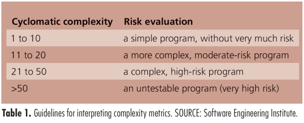
Complexity. Complex code is a fundamental sign of technical debt. Many legacy control systems have a few infamous code modules that are difficult to maintain. You may have heard statements such as, "No one understands how the recipe manager works" or, "The scheduler code is too fragile, only Steve can modify the scheduler." If these comments resonate, then you have experience with technical debt and the consequences of reduced ability to modify or enhance modules or poor reliability due to the inability to appropriately test the application. McCabe cyclomatic complexity is the most common complexity metric and many static analysis tools can easily calculate the measurements for your project. The Software Engineering Institute [3] publishes guidelines for interpreting complexity metrics (Table 1).
Click to Enlarge

Code duplication. When a code freeze is approaching, "cut and paste" can be a favorite approach in the developer’s bag of tricks. This is classic technical debt: shortcut, now, pay for your sins later.

Documentation debt. The next item that tends to get jettisoned at the release deadline, or during periods of tight development resources, is documentation. Developers are not known for being enamored with documentation in the first place. Lack of documentation does not directly affect the runtime characteristics of the software system, but missing design or test documentation needs to be counted as technical debt because there is interest to be paid.

Testing debt. Unit testing is another item that gets squeezed due to schedule pressure. The interest on this type of debt is the lack of a safety net to catch regressions. Current best practices in software development call for unit tests for all modules and for running all tests during continuous integration. Michael Feather calls this "code that bites back," [4] meaning that the system informs you (usually by email) if your submission just broke a unit test. Again, good code coverage tools exist to help you understand your testing debt.

Architectural debt. Architectural debt exists when the software architecture is no longer well-aligned with the key product drivers and this can happen in two ways. First, developers can cause architectural decay if they do not understand and follow the architectural rules and maintain the intended conceptual integrity. A good example is not following the architectural layering rules and perhaps introducing a circular dependency. The second path to architectural debt is when the product itself evolves well past the capability covered by the original architectural design. This often occurs with very successful products or product lines; if the market loves the initial product capability, it tends to want to leverage it in new applications and demands additional features, modifications and configurations.

Tracking technical debt

It is important to make these different types of debt visible. Some agile development teams use informal debt statements, written on index cards and posted on a bulletin board. Other organizations use a more formal tracking method which calls for developers to enter debt issues into the tracking system. This allows the organization to prioritize the issue and estimate the time for the required refactoring. It also allows the debt issues to be added to the schedule and to be managed like any other development task.

Another established, but simple, effective method is the use of a "pain dashboard" to track technical debt. This can be manifested as a wiki page where developers could easily add entries describing the parts of the system that are difficult to understand and debilitating to their productivity. The system can allow for a voting scheme so the team has a self-balancing mechanism to continually prioritize their technical debt.

Bankruptcy as the last resort

When faced with crippling financial debt, bankruptcy is always the last resort. We can extend the technical debt metaphor nicely here. For equipment control systems, bankruptcy occurs when you conclude that the legacy code base is a dead end and is no longer viable to support the forward-looking product roadmap. A complete rewrite and a new platform are needed for the organization to be competitive going forward. In this case, the technical debt can be retired along with the legacy system, and like filing Chapter 11, you are no longer responsible to address all the sins of the past.

Initially, this may sound like an attractive option, but the decision to undertake a rewrite should never be taken lightly. Developers rarely get the opportunity for a clean sheet redesign, and for good reason; it is expensive. Developing a new equipment software platform can represent an investment of perhaps millions of dollars.

Still, it is true that control system software does have a finite shelf life. If the existing equipment software is ten or more years old, there is a good chance that it does not leverage advanced off-the-shelf software technologies or modern design and architecture concepts. A redesign represents an opportunity to significantly increase the productivity of your software staff (with a resultant cost reduction) as well as a chance to retire a decade of technical debt en masse.

Benefits of paying down the debt

Your software control systems have, more likely than not, incurred significant technical debt during the economic downturn. It’s time to pay down the technical debt and your organization will benefit:

Increased R&D efficiency and improved time-to-market. Once the code base has been cleared of crippling technical debt, the development velocity will increase. The design refactoring is effectively cleaning the molasses out of your software development machinery. You can expect subsequent software modifications to be implemented more efficiently, and therefore, time-to-market for new features and new products will improve.

Hitting commitment dates. Paying down the technical debt will increase the team’s overall understanding of the code base. This will have the effect of getting better estimates for work to be completed and reducing risk during subsequent modifications.

Performance and technology upgrades. Another positive side effect of attacking the technical debt is the opportunity to upgrade to the latest technologies. This can mean moving to the latest versions of compilers and development tools. It can also mean upgrading to the latest versions of the operating system and third-party libraries and possibly even to a faster processor.

References

1.  http://c2.com/cgi/wiki?TechnicalDebt

2. M. Fowler,  http://martinfowler.com/bliki/TechnicalDebtQuadrant.html

3. Carnegie Mellon, Software Engineering Institute.  http://www.sei.cmu.edu/

4. M. Feathers, Working Effectively with Legacy Code. Prentice Hall, Englewood Cliffs, NJ, 2005.

Biography

Dan O’Connor received his MS in computer science from Boston U. and is a software architect at Foliage, 168 Middlesex Turnpike Burlington, MA 01803; ph.: 781-993-5500; email  [email protected].

More Solid State Technology Current Issue Articles
More Solid State Technology Archives Issue Articles

(June 30, 2010) — New TP-S30 thermal interface pads from MH&W International provide 3.0 W/mK of thermal conductivity between hot components and heat sinks at lower costs than competing gap filler materials. Pads of TP-S30 thermal gap fillers are soft and compliant for easy compression and filling of air gaps between mounting surfaces to optimize heat transfer. Applications for these gap fillers include alternative energy, consumer electronics, telecommunications, power supplies, flat panel displays, and portable electronics.

Pricing for standard TP-S30 gap filler material starts at $0.07 (0.5 mm thick) per square inch. Lower pricing is available for TP-S materials with lower thermal conductivities, i.e. 2.0 and 1.0 W/mK (TP-S20 and TP-S10). A low silicone content version, TP-S30LS, has less than 50 parts per million silicone content for applications where silicone-based outgassing can lead to contamination problems or oily silicone residues can hamper assembly. 

All TP-S series gap fillers are provided in 210 x 297 mm (8.3 x 11.7 inch) sheets or in standard die cut shapes. Custom shapes are available. Standard materials have a Shore 00 hardness of 45. Standard thicknesses range from 0.5 to 5.0 mm. All materials are UL94 V0 rated and have a use temperature range of -60° to +200°C.

MH&W International Corporation supports alternative energy, telecommunications, consumer electronics and power supply industries with products, technologies, and services that promote our customers’ immediate and long-term goals. For more information on TP-S thermal gap filler materials, visit http://www.mhw-thermal.com

June 21, 2010 – Analysis of the latest monthly sales & order data for US-based and Japanese semiconductor manufacturing equipment shows growth slowing down — and possibly because except for some pockets, it may be time for things to pull back a little bit.

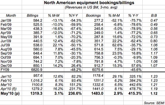
May chip tool sales totaled $1.48B, and billings were $1.32B, both up only about 3% from April. (Remember that SEMI uses a three-month moving average to smooth out inconsistencies in the data, e.g. an extra few days in certain periods.) Both still showed monstrous gains from a year ago (414% and 236% respectively), as much a verdict on a lousy 2009 as a boon 2010. The B:B ratio came in at 1.12, meaning $112 worth of orders was received for every $100 of product billed during the month.

  • Bookings are at their highest levels since June 2007. (For the first time all year, though, SEMI has not tacked on an extra $20M-$50M to its preliminary monthly tallies…a sign of changing times, perhaps?
  • Billings are also on a roll, with their highest level since April 2008.
  • The B:B has stayed above the 1.0 parity mark for eleven straight months, indicating that still more business continues to come in (orders) vs. go out (sales).
  • Bookings have increased sequentially in 13 of the past 14 months (with the only slide a -0.3% dip in Oct. 2009). For billings, the streak is 13 in a row dating to May 2009.


Click to Enlarge

With yet another month of growth — and metrics that seem to be slowing up — is it time to ask, when is the next downturn? (That’s what everyone wants to know — just ask Bill McClean!) Frontend bookings are within ~10% of the prior peak of June 2007 — and assuming wafer-fab equipment spending stays below 2007 levels, then by correlation bookings will not surpass that mark, claims Steve O’Rourke, analyst with Deutsche Bank. (Backend bookings, though, are beyond 2007 levels and approaching 2004 peak levels due to "a copper wire bonder buildout through the balance of the year.") He predicts that billings growth is now poised to overtake bookings, and pull the B:B down.

Meanwhile, in Japan, growth continues but also seems to be slowing. Orders for domestic semiconductor equipment rose 5.9% sequentially in May to ¥106.186B (US $1.17B) — 14 straight increases; while sales were practically flat (0.7%) at ¥94.233B ($1.04B), 11 straight growth months. The B:B ratio rose back up a little bit to 1.13, the 12th straight month above parity. Here, bookings growth is still well below 2007 levels — partly due to domestic companies losing market share in etch (TEL to Lam Research) and lithography (Canon, Nikon to ASML), O’Rourke notes.

by James Montgomery, news editor

June 14, 2010 – Samsung’s announcement that it has completed testing of its 32nm high-k/metal gate architecture, ramping to volume possibly by year’s end — and following quickly with a 28nm version — has the industry buzzing about a possible reshaping of leading-edge semiconductor foundry manufacturing.

Ana Hunter, VP foundry at Samsung Semiconductors, filled in some of the details for SST. The Samsung 32nm process is a gate-first HKMG structure based on the IBM common platform. An SoC application processor "designed for maximum testability" — the same one used by Samsung for its 45nm low-power process, for an apples-to-apples comparison — improves dynamic power reduction by 30% and leakage power by 55% (thanks to things like power gating, multi-threshold voltages, multi-channel lengths and adaptive body biasing techniques). It incorporates an ARM 1176 core, with physical core library, cells, memory compilers, etc. designed by ARM. Also included is a Synopsys IP macro, plus other Samsung-designed IP basically used to qualify the ecosystem process; Samsung also is working with EDA partners (e.g. Synopsys, Cadence, Mentor) to make sure everything works with design kits and tools that its customers already use. Everything at 32nm HKMG can be migrated to 28nm, Hunter said; design rules are shrinkable with recharacterization and timing.

Gate-first HKMG is easier to implement as a transition from a traditional poly/SION structure, Hunter explained. The construction of the gate and transistor remain the same, though the materials are different (i.e., a high-k gate oxide instead of oxynitride); a metal gate is inserted, and then poly on top of that — and the rest of the flow is "basically the same as previous generation structures," she said. Compared with gate-last HKMG, gate-first also is "much simpler" to implement from a process migration standpoint in terms of IP implementation, and fewer restrictive design rules (gate-last requires CMP around the gate structure). Gate-first enables good logic density shrinking — "we can maintain 50% shrink from 45nm to 32nm because there’s not as many restrictive design rules," Hunter said. This makes the process particularly good for mobile applications, as it’s cost-effective and "very good on gate leakage — >100× improvement from 45nm to 32nm."

After early process development w/ the alliance, Samsung installed the technology in its S line in Korea (on which the company also does LSI work), completed qualification and reliability testing (wafer-level, package-level, 1000 hour stress testing) with materials manufactured on the S line, to improve yield and manufacturability, noted Hunter. Tape-out will be in the next few months. with primarily prototyping and customer sampling in 2H10, and production in early 2011 (or possibly pulled into the very end of 2010). "The process is frozen," Hunter said; what remains is "getting yield up, getting more tools qualified, bringing up the manufacturability side of things." She also confirmed that the 28nm HKMG version "is still on schedule to be production-ready in 1H11." (That’s about in line with what Samsung said late in 2009, and Hunter reiterated in April in a podcast with SST‘s Debra Vogler, that 32nm/28nm HKMG was in "preparation" for volume production with tapeouts later in the year and moving "very quickly to 28nm.")

Click to Enlarge
Ana Hunter, VP foundry, Samsung Semiconductors

Why do both 32nm and 28nm; Samsung’s foundry differentiators; CPA pros/cons

Pros/cons of its HKMG process being based on the IBM Common Platform Alliance: "We develop the process jointly, provide customers the ability to multisource in different factories with competitive business models…Of course we compete for business, but we think the foundry market is a big market, growing all the time." With another company based on the same technology, and options to do other things (e.g. additional modules, customize processes) — "having that baseline being able to source at both suppliers, working together to ensure GDS compatibility, is a major competitive advantage. There’s plenty of business out there for us both."

What’s the strategy to compete with TSMC: "Obviously we have not been in the foundry business as long as TSMC has, and we’re nowhere near as big. Our strategy is to be very competitive in advanced technology nodes. To that end, we are very focused on achieving leadership in advanced nodes — not just development but taking it to high-volume manufacturing, because we have the financial capability to do so."

"Getting into the business to be a second source is not our intention."

Why strongly pursue both 32nm and 28nm HKMG: The strategy is to be "all-in at 32nm and smooth the way for 28nm," Hunter explained. "We thought it was important to meet the needs of customers who want 32nm now, an advantage in time-to-market, then follow close with 28nm." Planting the HKMG flag first at 32nm "makes us a leader…we think that’s important to have competitive position there, to invest in these technologies, to bring to production in high-volume fabs," she said. And getting HKMG under its belt early and fast, and ramped to volume, is particularly important so that customers are "comfortable with manufacturability and cost savings," especially for low-power target end-applications like mobile devices, she noted. "Having 32nm in production will help us a lot with the learning curve, making 28nm a much smoother transition," Hunter said.

Differentiators for Samsung’s foundry business: If a customer needs help with a design, Samsung’s Hunter sees this as a differentiator: "We do that work in silicon and real products, and feed that learning back into design flows that we can provide our foundry customers." Samsung also has ASIC services for customers who want to have backend design work done. "The line between ‘ASIC backend’ and foundry is becoming fairly gray and fuzzy; customers are more and more seeking help on the design side [which is] getting very complex," Hunter said. "DFM built into design is something we’re experts in."

Supporting foundry with capex. Note that Samsung’s recent capex blitz for 2010 included about $1.8B for its system LSI operations, within which the foundry business is a subset. (Hunter offered no definition as to how that’s split up — Gartner’s Dean Freeman suggested the foundry portion could be up to $1B.) Hunter did say that the new investments are "very beneficial for our foundry business," being in advanced technology nodes and 300mm lines "where our foundry business is concentrated." Also, Hunter noted that the $1.8B pie is only for manufacturing lines — and suggested there’s another 8T won (almost US $7B) in R&D capex budget that could be tapped as well.

Analysts’ take: Finally, a foundry horse-race!

Samsung isn’t the biggest foundry, and the question of who’s "first" with HKMG is still up for grabs — but certainly its announcement of production-ready 32nm HKMG and a 28nm version soon to follow has complicated the equation for leading-edge semiconductor manufacturing options.

TSMC has been talking about HKMG but has set its bar at what traditionally have been viewed as "half-nodes," e.g. 40nm and 28nm, notes Joanne Itow with Semico Research. TSMC’s 40nm process offered "a slightly different formula for power and performance" — but there were some openly known yield issues that caused headaches and poor publicity, she added. Gartner’s Freeman suggested no foundry has "completely ditched" 32nm HKMG in favor of 28nm — TSMC is running an abridged version for those who want it, and GF has a 32nm offering as well, but "they don’t talk a lot about it as they are both moving to the half-node where the foundry money is."

So which foundry will be first with 32nm/28nm HKMG, and when? Samsung says it will have 32nm HKMG ready by late 2010 or early 2011 — earlier this year it identified Xilinx as the first customer for 28nm HKMG, and Hunter told SST that "there are others" both existing and new customers (but she wouldn’t name names). Qualcomm is another leading-edge customer for Samsung, and so is Apple (Samsung fabbed a chip for the iPad); "You also might see Infineon with a device or two," Freeman suggested. Meanwhile, GlobalFoundries will have a 32nm HKMG version ready in 4Q10, which is a MPU for AMD using an SOI process — though it’s unclear if/when a 32nm HKMG foundry process will be available. In January TSMC said Qualcomm would tape out a 28nm process in mid-2010, but wasn’t specific whether that would be HKMG or SION. Almost a year ago it said it would start ramping 28nm HKMG process (first a HP version, then LP) in 3Q/4Q10. TSMC and GF roadmaps are very similar, Freeman said, so rollouts could be separated by only a month or two.

"Due to the way roadmaps are announced it will be difficult to tell who will really be first until someone announces a customer is shipping in some sort of volume," Freeman said.

The greater message may be that the foundry sector is finally becoming a horse race. Though TSMC will likely ramp its HKMG option first, its lead on others has notably shrunk, says Freeman. "What we have at 32nm/28nm is the real beginning of what I have been calling the foundry wars" — GlobalFoundries and the Common Platform Alliance trying to unseat TSMC, and TSMC firing back. "The differentiation will be who can provide the design service I need, Meet my capacity requirements, and hit my technology roadmap," Freeman said.

Judging just based on research, "I believe the foundries are neck and neck — and that includes Samsung," said Itow. For actual deliverables, TSMC would still lead the pack but with GF and Samsung right behind. "I’d compare this to a horse race that requires a photo finish to determine the winner," she said. "And actually, there probably aren’t any losers in this race — the customers are provided more variety with lots of proven technology."

In a system-in-package (SiP) chip stack, space constraints can lead to large parasitic inductances in the packaging. Planarity, processing, high-temperature exposure, and other factors also present challenges. A new anisotropic conductive adhesive technology could enable low-cost flexible packaging via a multi-layer particle structure. S. Manian Ramkumar, Ph.D., RIT, reviews the adhesives benefits to various levels of electronics interconnect.

The electronics industry is continuing its push for product miniaturization and RoHS compliance through innovative component technologies, PCB assembly technologies, and materials. For portable consumer products like flash, MP3 players and heterogeneously integrated RF systems, chip stacking using a system in package (SiP) approach is becoming more popular. In these space-constrained applications, conventional packaging techniques become very complex, and result in large parasitic inductances. Other challenges such as planarity, extra processing steps, and high temperatures arise while using a bumping and flip chip bonding approach. These challenges have renewed the industry’s interest in exploring the use of electrically conductive adhesives (ECAs) for various applications at the component packaging level and also at the lead-free PCB assembly level.

A novel anisotropic conductive adhesive (ACA) is currently available in the market to address these challenges and provide a means for low-temperature flexible packaging. Referred to as the ZTACH ACA by its manufacturer, the novel ACA uses a magnetic field during thermal or UV curing to align the particles as columns in the Z-axis direction (Figure 1). This method of aligning the particles as columns eliminates the need for pressure during assembly, to capture conductive particles between the mating surfaces. Unlike a conventional ACA, more than one particle is typically captured between the opposing surfaces with ZTACH. The formation of conductive columns eliminates bridging between adjacent pads, and has proven to accommodate varying lead configurations. Modification of the filler size and filler proportion enables control of the column density, column spacing, and the required contact pad area for minimum resistance. The novel ACA also enables mass curing of the adhesive, eliminating sequential component assembly. The ZTACH ACA offers numerous benefits for SiP assembly, including thin form factor, low assembly cost, and low parasitic impedances for high data rate, high-frequency applications. Unlike traditional ACAs, ZTACH ACA has a low parasitic capacitance because of the multilayer-particle structure after curing.


Figure 1.

The ZTACH material is being researched at the Center for Electronics Manufacturing and Assembly (CEMA) at the Rochester Institute of Technology (RIT) and at the IDEAS lab at Purdue University. The novel ACA’s applicability for PCB-level assembly has been successfully demonstrated by RIT. The research at RIT has also characterized the base material properties, analyzed the effect of various process parameters, identified failures, and investigated the ACA’s long-term reliability for surface mount PCB assembly. Specific characterization and analysis carried out by RIT include process parameters such as print thickness, placement speed, pressure and dwell, cure temperature and time, magnetic field strength, substrate finish, component termination finish, and leaded or bumped packages of varying configurations. Reliability testing included an investigation of the assembly performance in temperature and humidity aging, thermal aging, air-to-air thermal cycling, and drop testing conditions. The IDEAS lab at Purdue University has been using ZTACH to successfully implement highly integrated RF SiP modules using novel concepts such as reverse pyramid stacking and nested chip stacking. The Purdue research has also demonstrated that chip-to-chip silicon wafer interconnects assembled by manually dispensing ZTACH, without any additional preparation for individual chip I/O pad bonding, show very good RF performance, up to 90 GHz.
 
Thermal aging of the novel adhesive material has revealed improvement in contact resistance. Area array packages, with and without bumps, have shown variations in performance and have revealed the importance of placement pressure, speed, and dwell in achieving low initial contact resistance. Area array packages with bumps have provided consistent performance with low contact resistance. A mathematical model has been developed to model the column formation and prove its validity with experiments. The research published by RIT also indicates that immersion silver (ImAg), electroless nickel immersion gold (ENIG), hot air solder leveling (HASL), and organic solderability preservative (OSP) finishes outperform immersion tin (ImSn) finish during temperature/humidity aging. The research by the Purdue group has demonstrated successfully the use of ZTACH to package Tx silicon board for biomedical applications, such as the study of glaucoma in rabbits and mice. Note that glaucoma is predicted to affect about 60.5 million people by 2010. Biomedical implantable micro-systems, used in the study of medical conditions such as glaucoma, require exceptional levels of integration (300 × 300 × 300 µm3) and low profile (<50 µm), along with bio-compatibility. These features make ZTACH suitable for the 3D packaging required in these applications.

1. ZTACH is a trademark of SunRay Scientific, www.sunrayscientific.com

S. Manian Ramkumar, Ph.D., is an SMT Editorial Advisory Board member and professor and director at the Center for Electronics Manufacturing and Assembly (CEMA) at Rochester Institute of Technology (RIT). Contact him at [email protected]; http://smt.rit.edu. In the discussion of the novel ACA’s properties, Dr. Ramkumar fully discloses that he holds a small equity stake in SunRay Scientific. The material properties discussed here were derived from unbiased university testing at RIT under fully established compliance procedures and Purdue and not influenced by the company.

Advanced Packaging, June 2010, http://www.electroiq.com/index/packaging.html

Also read:


The second wave of 3D packaging technology: PoP

PoP, together with WSP and QFN, have been the industry’s most successful packages during the last decade, and their success will extend into this decade. Mario A. Bolanos, Texas Instruments Inc.

Electroless NiAu on thinned wafers enables cost efficient prototyping

The electroless deposition of nickel and gold (ENIG) is a well established process for printed circuit board manufacturing; applied to electronic wafers, it offers a cost efficient under bump metallization for soldering, Ag sintering or gluing applications. Dirk Kähler, Fraunhofer Institute for Silicon Technology ISIT, Itzehoe, Germany


(May 26, 2010) MONT-SAINT-GUIBERT, Belgium — High-temp semiconductor provider CISSOID, along with the 13 other members of the consortium, jointly announced the CREAM European project. The CREAM Project addresses the thematic “Aeronautics and Air Transport (AAT)” through the objective of developing an “Innovative Technological platform for Compact & Reliable Electronic integrated in Actuator and Motor” destined for several applications of the All Electric Aircraft such as fuel pumps, landing gear or brake actuators, flight control actuators, etc.

The CREAM project is supported by the European Commission through the Seventh Framework Programme (FP7) for Research and Technology Development with around 4.2M€ of grant out of 6.2M€ total budget. It started on the first of September 2009 and will last until the end of August 2012.

The CREAM project requires multi-disciplinary expertise shared between 14 partners (research centers, universities, SMEs, and large industries) from 10 countries. These partners include SAGEM (France), HISPANO-SUIZA (France), SEMELAB (UK), AIT (Austria), EPFL (Switzerland), ADVANCED SILICON (Switzerland), LEM (Switzerland), CISSOID (Belgium), Fraunhofer-Gesellschaft (Germany), TEIP (Greece), NATUREN (Hungary), UAC (Russia), ROTECH ENGINEERING (Greece), and ALMA Consulting Group (France).

The political, environmental and economical trends for air transport are leading towards the all electric aircraft (AEA), state the CREAM consortium members. They note that electrifying aircraft creates opportunities to reduce weight, which leads to reduced carbon dioxide emissions and also to reduced maintenance costs. To design the AEA, the goal is to eliminate as many hydraulic power sources and complicated circuits of high-pressure hydraulic lines as possible. Replacement of conventional hydraulic systems will take place through the replacement of all hydrostatic actuators with electro-mechanical actuators (EMA) such as flight control actuators, braking system, landing gear actuators, propulsion inverters, various pumps, various auxiliary actuators, etc.

The real challenge, according to CREAM, is the development of compact, reliable, electrically powered actuators. The CREAM project will develop and validate various emerging sub-components, packaging, and motor technologies to integrate them into a high-performance smart electronic and motor technological platform destined to electric actuator preparation.

This technological platform will offer a panel of emerging semiconductor packaging technologies such as diamond copper substrates, flip chip assembly technologies, elimination of base plate, new magnetic material with higher magnetic properties and innovative thermal management system concepts.

The CREAM project targets new high-performance and reliability capabilities of electro-mechanical actuators (EMA) in harsh thermal environmental conditions (over 200°C), ready for use in all-electric aircraft.

Immediate benefits of the CREAM Project with electrical power and electronics in actuation include higher performances and reliability, benefits of overall weight reduction (optimization of power/weight ratio), easier maintainability, reducing operating costs (including reduced fuel burn), and enhanced safety.

Further information about the events, publications and the project consortium are available under the project public webpage www.creamproject.eu

Read more about Packaging Technologies

Read more about Aerospace Electronics