Category Archives: LEDs

January 26, 2011 — An international team of scientists led by King’s College London has taken a step closer towards developing optical components for super-fast computers and high-speed Internet services of the future. This has the potential to revolutionize data processing speeds by transmitting information via light beams rather than electric currents.

Click to Enlarge
Artistic impression of metamaterial structure consisting of gold nanorods illuminated by two interacting light beams. Courtesy of R. McCarron

The researchers are studying the science of ‘nanoplasmonic devices,’ whose key components are tiny nanoscale metal structures, more than 1000 times smaller than the size of a human hair, that guide and direct light.

Information is routinely sorted and directed in different directions to allow computing, Internet connections, or telephone conversations to take place. At present, however, computers process information by encoding it in electric signals.

It would be much faster to process and transmit information in the form of light instead of electric signals, but until now, it has been difficult for the light beams to be ‘changed,’ that is to interact with other beams of light, while travelling through a material, and this has held up progress.

The scientists have solved this by designing a new artificial material, which allows light beams to interact efficiently and change intensity, therefore allowing information to be sorted by beams of light at very high speeds. The structure of the tailor-made material is similar to a stack of nanoscale rods, along which light can travel and interact.

Professor Anatoly Zayats, in the Department of Phyics at King’s, explains: "If we were able to control a flow of light in the same way as we control a flow of electrons in computer chips, a new generation of data processing machines could be built, which would be capable of dealing with huge amounts of information much faster than modern computers.

"The new material we have developed, often called ‘metamaterial,’ could be incorporated into existing electronic chips to improve their performance, or used to build completely new all-optical chips and therefore revolutionize data processing speeds.

"While there are many challenges to overcome, we would anticipate that in the future this faster technology could be in our PCs, mobile phones, aeroplanes and cars, for example."

Other members of the team involved in this latest research include Argonne National Laboratory in the USA; University of North Florida; University of Massachusetts at Lowell; and Queen’s University of Belfast in the UK.

The Engineering and Physical Sciences Research Council (EPSRC) is funding the £6 million research programme at King’s, Queen’s University Belfast and Imperial College London.

The research is published in the journal Nature Nanotechnology. The paper ‘Designed ultrafast optical nonlinearity in a plasmonic nanorod metamaterial enhanced by nonlocality’ is published on Nature Nanotechnology’s website at http://www.nature.com/nnano/journal/vaop/ncurrent/full/nnano.2010.278.html

For further information, visit http://www.activeplasmonics.org/ 

King’s College is research led and has nearly 23,000 students (of whom more than 8,600 are graduate students) from nearly 140 countries, and some 5,500 employees. King’s is in the second phase of a £1 billion redevelopment programme transforming its estate.

Follow Small Times on Twitter.com by clicking www.twitter.com/smalltimes. Or join our Facebook group

January 26, 2011 Light-emitting diodes (LEDs) are an increasingly popular technology for use in energy-efficient lighting. Researchers from North Carolina State University have now developed a new technique that reduces defects in the gallium nitride (GaN) films used to create LEDs, making them more efficient.

LED lighting relies on GaN thin films to create the diode structure that produces light. The new technique reduces the number of defects in those films by two to three orders of magnitude. "This improves the quality of the material that emits light," says Dr. Salah Bedair, a professor of electrical and computer engineering at NC State and co-author, with NC State materials science professor Nadia El-Masry, of a paper describing the research. "For a given input of electrical power, the output of light can be increased by a factor of two." This is particularly true for low electrical power input and for LEDs emitting in the ultraviolet range.

Figure. The new technique reduces the number of defects in those films by two to three orders of magnitude — increasing the output of light by a factor of two for a given amount of power. (Image courtesy of Lukasz Tylec)

The researchers started with a GaN film that was 2

January 26, 2011 – PR Newswire — Steed Technology, thermal processing equipment provider for semiconductor, LED, and solar cell manufacturers, acquired all of the outstanding stock of Applied Technology Specialists, Inc. (ATSI), an advanced engineering firm that specializes in developing advanced pollution control equipment and technology to render safe volatile organic compounds (VOCs) and toxic exhaust gases found in high-tech industries.

As part of the acquisition, both companies will share the Steed name. The manufacturing of all products will remain in Northern California with research and development of new products and technologies remaining in Oklahoma. Sales channels will be expanded both domestically and internationally to accommodate existing and new customers, focusing on regions with new air quality restrictions.

With the acquisition, Steed will incorporate the ATSI EcoGuard line of Point of Use (PoU) gas abatement/scrubber and pollution control equipment. Steed is currently working to combine these technologies to work in unison. Customers of Steed and ATSI will soon be able to purchase diffusion/LPCVD process and abatement equipment as a totally integrated system with onboard environmental control features developed by ATSI.

With new, increasingly strict, environmental regulations such as the Greenhouse law (AB32), many companies in the semiconductor, LED, solar and other industries are closely examining ways to increase the effectiveness and efficiency of their current abatement systems. Environmental control will play a major roll with manufacturing companies in the years ahead. To help meet this need Steed will, in addition to offering products that help companies meet such strict requirements, offer Green consulting and solutions services to help companies reduce emissions of gasses such as Perfluorocarbons (PFCs), Oxides of Nitrogen (NOx), and Carbon dioxide (CO2), to levels that comply with local and federal laws, while reducing consumption of utilities such as fuel and water. The merger adds considerable value to this consulting service through the addition of the ATSI solutions team with a combined 50 years of gas abatement and clean-air solutions experience.

Existing abatement solutions aim to scrub then dispose of hazardous byproducts created during the production of LCDs, semiconductors and solar cells. With increasing regulations, and the high cost associated with utilities such as power and water the common "wet scrubbers" and "chemical adsorption" methods utilized by such technologies have become inefficient. Steed’s EcoGuard products are designed to destroy and eliminate hazardous by-products, vs. capturing the by-products for further, costly, hazardous waste disposal. Steeds abatement product line also offers a low-operating-cost solution for process and abatement savings through an innovation known as the "On-Demand" Control Program. Using sensor-driven process signals, operators can control the type of abatement required for the particular gas and only use what is necessary to abate and emit clean air to the environment.

Steed Technology provides thermal processing equipment and environmentally responsible Point of Use (PoU) gas abatement products for the semiconductor, LCD and solar industries. Learn more at www.steedtech.com

Subscribe to Solid State Technology/Advanced Packaging.

Follow Solid State Technology on Twitter.com via editors Pete Singer, twitter.com/PetesTweetsPW and Debra Vogler, twitter.com/dvogler_PV_semi.

Or join our Facebook group

January 24, 2011 — KLA-Tencor Corporation (NASDAQ: KLAC) debuted an automated inspection system for substrates and epitaxial wafers used in high-brightness LED (HBLED) manufacturing. The Candela 8620 provides automated defect inspection for LED materials such as gallium nitride, sapphire, and silicon carbide, enabling enhanced quality control of both opaque and transparent substrates, faster time-to-root cause, and improved metal organic chemical vapor deposition (MOCVD) reactor uptime and yield. Frank Burkeen, VP & GM of the Candela Division at KLA-Tencor, discusses the Candela 8620 inspection system.

Listen to Burkeen’s interview: Download (iPhone/iPod users)  or Play Now

In the interview, Burkeen cites data made available in a Department of Energy (DOE) study and also addresses the importance of detecting process excursions faster. The differences between silicon CMOS manufacturing and LED manufacturing are also discussed.

Click to Enlarge

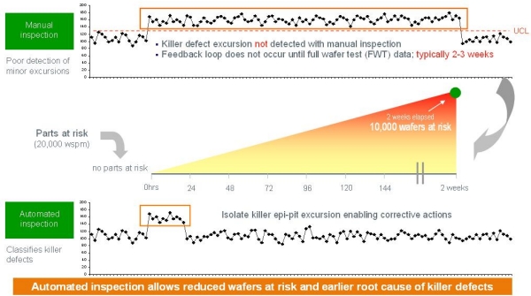
Figure 1. Example of the impact of faster excursion detection (manual inspection vs. automated inspection). SOURCE: KLA-Tencor

With its proprietary optical design and detection technology, the Candela 8620 detects and classifies sub-micron defects that are not consistently identified by current inspection methods, according to KLAC. The recent DOE study is exciting, Burkeen says, because it shows that to achieve the cost reduction targets for SSD lighting to make it into the general lighting arena (about 10× cost reduction), process control, better methodology around defect inspection and root cause analysis is needed. Yield can be responsible for making up half of that cost difference.

In LED manufacturing, just growing the epi layers — the first part of the front-end process — accounts for about half of the value of the device, before you’ve even started fabricating the device, said Burkeen. According to industry sources, as HBLED manufacturers transition production to larger wafer sizes and introduce new patterned sapphire substrate (PSS) processes, the economic impact of resulting process-induced defects is estimated at millions of dollars in lost product revenue per year, and MOCVD epi process issues may result in as much as 40% of overall defect-induced yield loss. Quantum wells are constructed during the epi deposition and they determine the wavelength and luminosity of the device. "This is much different from silicon CMOS processing in which much of the value added occurs later in the process (as the structure is built with circuit lines)," observed Burkeen. Therefore, process control around an early step [in LED manufacturing], when the wafer is unpatterned, has a much greater significance than it would in CMOS manufacturing, he said (Fig. 1).

Click to Enlarge

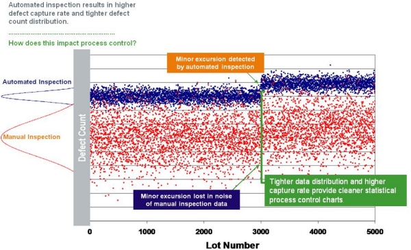
Figure 2. Excursion detection: impact of capture rate and tighter data distribution. SOURCE: KLA-Tencor

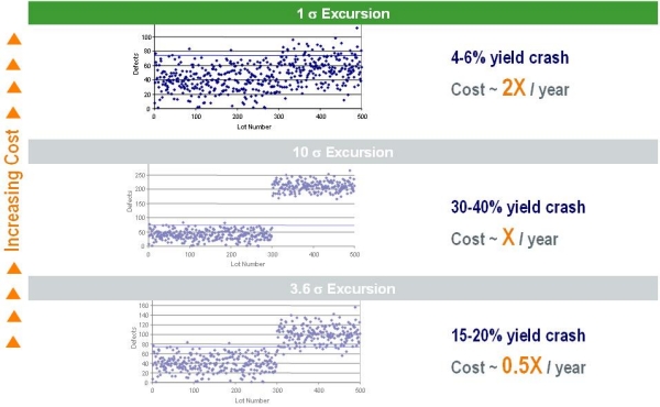
Burkeen also explained how automated inspection results in higher defect capture rate and a tighter defect count distribution (Fig. 2). Being able to produce a much tighter distribution with coverage of the full wafer gives you much more sensitivity to small excursions, noted Burkeen. An operator with manual inspection has virtually no sensitivity to a small excursion because of the area they are looking at, variability, etc. "Financially, a small excursion that is hard to catch, is really the most dangerous type for your financial performance as an LED manufacturer," said Burkeen (Fig. 3). LED substrate and epitaxy layers pose significant inspection challenges due to high levels of background signal and nuisance defects. The Candela 8620’s imaging and detection system is optimized to enhance the signal from relevant defects-of-interest while suppressing background noise. Aided by its multi-channel detection optics, the system additionally allows high purity classification of such defects, allowing comprehensive statistical process control of critical MOCVD processes.

Click to Enlarge

Figure 3. Economic impact of major vs. minor excursions. SOURCE: KLA-Tencor

The Candela 8620 can detect:

  • Substrate defects such as micro-scratces and micro-cracks which can create epi process defects and directly impact LED yield and reliability
  • Defect sources from lithography and etch processes for patterned sapphire such as missing bumps and resist voids, resulting in epi defects or reduced lumen output
  • Macro- and micro- defects in MOCVD processes, including hexagonal pits and bumps leading to electrical failure, and epi cracks which can adversely impact field reliability.

KLA-Tencor also debuted the KLARITY LED automated analysis and defect data management system and ICOS WI-2220 wafer inspection tool designed specifically for LED defect inspection.    

KLA-Tencor Corporation provides process control and yield management solutions with inspection and metrology technologies. These technologies serve the semiconductor, data storage, LED, photovoltaic, and other related nanoelectronics industries. Additional information may be found at www.klatencor.com. (KLAC-P)

by James Montgomery, news editor

January 24, 2010 – At the Common Platform Technology Forum (Jan. 18 in Santa Clara, CA), execs declared that they will switch from a gate-first approach to a gate-last approach starting with the 20nm process technology node, essentially reversing their position stated for years now. Analysts told SST why the CPA had a change of heart, why it’s not unexpected, and why other concerns will very soon overshadow this switchover.

There’s been a schism about gate structure at the ≤32nm node: a camp of gate-first proponents, led by IBM and CPA partners, and a gate-last approach being implemented by Intel as well as TSMC (and UMC has a hybrid approach). Each side claims benefits and ways to deal with drawbacks. "Gate first is simpler and lower cost as the conventional flow, but Vt tuning and thermal budget are critical," summed Gartner foundry analyst Sam Wang. "Gate last can use spacer for stress tuning and mobility enhancement, but has more complex process and design rules." Gate-first has an edge with low-power dissipation devices; gate-last is more ideal for high-performance ones.

Chipworks’ Dick James has a great technical explanation of the gate first-vs.-last history and why gate-last is (for now) the winner. But what else can we take away from this?

— It wasn’t needed at 28nm… According to the IBM-led CPA, gate-first was a better choice at 28nm for a number of reasons: scalability relative to 40nm, enjoying less restrictive 40nm layout style advantages, faster speed and reduced energy/switch, and a smaller die vs. a gate-last approach. Vt tuning range (>>300mV) can be done with process knobs, and it offers repeatable low- and superlow-threshold voltage options.

Gate-last proponent TSMC, meanwhile, offers a number of gate-last arguments of its own: speed, power, reliability, manufacturability, and scalability. Device power consumption can be minimized with process knobs, it says, and threshold voltage is kept stable via thermal processes done before HKMG deposition.

…But it’s inevitable at 20nm. While the jump from 40nm to 28nm was seen as perhaps easier using a gate-first approach, "the arguments regarding leakage and performance probably couldn’t be ignored at 20nm," said Gartner research VP Dean Freeman. Added James: "My take is that the gate-first guys underestimated the difficulties of making a stable process […and] it’s turned out to be a real pain." Gate-last is a more complex process flow — there is added mask and CMP work, plus workfunction by using different metals instead of doping them, noted Freeman. But Intel has shown that it’s manufacturable even with the extra CMP of the gate stack, "and TSMC and UMC wouldn’t have gone that way if they didn’t think the same," James said. And the argument against gate-last’s more restrictive design rules becomes moot at 20nm which will demand them anyway, so "you might as well bite the bullet and switch to gate-last," he said.

It’s no big deal, compared to other things. The Common Platform Alliance says that it’s been evaluating both gate-first and gate-last since 2001 (gate-first was selected back in 2004). Speaking at the CPA forum, Gary Patton, IBM VP, said the replacement gate process isn’t his primary concern at 20nm — it’s other things that will come into play including self-aligned contacts, local interconnects, and BEOL pitches.

Patton noted that early 20nm production is slated for 1Q13, using third-generation ArF immersion litho with double patterning and source-mask optimization (SMO) technology. The SMO, along with special mask design software, is key to their 20nm process, explained Gartner research VP Bob Johnson, because it allows fine-tuning of both the mask and light source. "My impression is that IBM and its partners have much more experience" implementing these technologies, he said. Chipworks’ James points out, though, that forms of SMO are already being used (e.g. dipole sources), Intel has talked about it — "and ASML have now made onto their supplier list."

It’s not over yet. The debate over gate-first vs. gate-last likely will get revisited again soon, as another tough technology choice is coming right around the corner at 14nm, says Gartner’s Wang. That node will require fully depleted structure, which can be made either with FinFETs or extremely thin SOI (ETSOI). The IBM-led CPA has championed use of SOI so they’d have a leg up there, while Intel and TSMC are on bulk CMOS and would likely choose FinFET, he suggested. Once again it’s a case of pros vs. cons: gate-first pushes transistor engineering limits, but gate-last is more challenging in terms of fab work. So while gate-last appears to be the winner at 20nm, beyond this node it’ll be up in the air again.

January 21, 2011 – JCN Newswire — Professor Kohei Itoh, who is developing quantum computers based on silicon semiconductors at Keio University’s Faculty of Science and Technology, together with Dr. John Morton at Oxford University and others, successfully generated and detected quantum entanglement between electron spin and nuclear spin in phosphorus impurities added to silicon. This accomplishment constitutes a major breakthrough toward the achievement of quantum computers.

"According to Moore’s Law, which serves as the index for semiconductor microfabrication, by 2030, individual atoms in silicon will be used for computing," commented Professor Itoh. "The question of whether that kind of computing is possible was the starting point for my research, and as a way of approaching that question, I began to research computing using atoms in silicon. Now, we’ve performed the first successful experiment on computing using phosphorus atoms in silicon, and been able to create a special state called quantum entanglement. I am glad that this research has led to a world-first result: computing using atoms in silicon, the most important semiconductor."

The results of this research were featured in the British science journal Nature (online edition) on January 19, 2011.

Quantum computers work using entirely different principles from current computers, enabling new characteristics. Quantum superposition and entanglement drive the technology. Classical computers can only use states corresponding to one or other of the binary digits 0 and 1. By contrast, quantum bits, the minimum units for quantum computers, consist of individual quanta, in the form of atoms, electrons, and photons, and can represent 0 and 1 at the same time (superposition state). Another prerequisite for quantum computers is entanglement between at least two quantum bits. In an entangled state, individual quantum bits are entangled in a way that transcends space, so they cannot be separated and treated as 0 or 1.

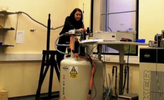
Click to EnlargeThis joint research by Keio University and Oxford University has achieved the first successful production and detection of entanglement in silicon. Phosphorus impurities are added to silicon to produce n-type silicon. Phosphorus atoms in silicon at low temperatures, less than 20K, capture an electron and behave like hydrogen atoms. Using this characteristics, the joint research group has produced and detected entanglement between two quantum bits by treating the nuclear spin of a phosphorus atom as one quantum bit and the captured electron’s spin as another quantum bit. The entanglement was produced at once for each of a large number of phosphorus impurities that exist in the sample in the order of 10 to the power of 10. The process of generating entanglement itself is equivalent to quantum computing.

Previously, coherence of quantum bits in silicon was too short. In ordinary silicon, the quantum information in phosphorus impurities is lost before entanglement is generated and measured. Keio University made coherence sufficiently long by ensuring that all the atoms in the silicon were the isotope 28Si, while a special magnetic resonance (MR) apparatus belonging to Oxford University produced a field of 3.4 Tesla at a temperature below 3K, to obtain high polarization of electron spin and nuclear spin in phosphorus.

In response to the question "What is a state-of-the-art quantum computer?", the usual example cited is a nuclear magnetic resonance (NMR) result with seven quantum bits, where the prime factorization 15 = 3 x 5 was performed successfully [L. Vanersypen, et al., Nature Vol. 414, 883 (2001)]. However, in the NMR research, the same number of calculation steps as in a classical computer was required to make it seem as if seven quantum bits in molecules were aligned, and entanglement was not obtained. By contrast, in this research, by using a low temperature and high magnetic field, and careful arrangements for quantum computing, quantum bits were initialized in a very small number of steps, and entanglement was successfully generated and detected. The entanglement state found in a large number of phosphorus atoms added to silicon constitutes a major breakthrough toward a solid-state quantum computer.

This research was conducted as part of "Quantum spintronics based on donor impurities in isotope-controlled silicon" (research representative in Japan: Prof. Kohei Ito; research representative in the UK: Dr. John Morton), a project in the JST’s "Strategic International Cooperative Program" with the UK’s EPSRC.

Entanglement can be explained with the example of two spatially separated quanta, in London and Tokyo. Suppose that, in both Tokyo and London, a quantum bit is in a superposition state, where its value is both 0 and 1. If the state is determined from before it is measured, but not known until it is measured, the bit is in a classical state, not a quantum state. In a quantum state, before the quantum bit is measured, its state is both 0 and 1, but the instant the state is measured, it becomes a classical state of 0 or 1. Measuring the quantum bit turns it into a classical bit. A case where there is a correlation between the bits, so if the quantum bit in Tokyo is measured and the value 0 is obtained, the quantum bit in London must be 1, and if the Tokyo bit is 1, the London bit must be 0. This is also called entanglement, as the two bits cannot be separated. Even though each of the bits, in Tokyo and London, has a state that is both 0 and 1, the instant the bit in Tokyo is measured and takes the classical state 1, it is determined that the London bit has the value 0. This correlation, which transcends space, exemplifies the mysterious nature of quantum mechanics, which cannot be explained using classical mechanics.

Keio is Japan’s first private institution of higher learning.

Japan Science and Technology Agency (JST) is an integrated organization of science and technology in Japan that establishes an infrastructure for an entire process.

Subscribe to Solid State Technology/Advanced Packaging.

Follow Solid State Technology on Twitter.com via editors Pete Singer, twitter.com/PetesTweetsPW and Debra Vogler, twitter.com/dvogler_PV_semi.

Or join our Facebook group

January 20, 2011Dow Corning has formalized an agreement to enter the imec multi-partner industrial R&D program on GaN semiconductor materials and device technologies. The program focuses next-generation GaN power device and LED development. The collaboration between Dow Corning and imec will concentrate on bringing the GaN epi-technology on silicon wafers to a manufacturing scale.

Click to Enlarge

Due to the combination of superior electron mobility, higher breakdown voltage and good thermal conductivity properties, GaN/AIGaN heterostructures offer a high switching efficiency for next-generation power and RF devices compared to the current devices based on silicon. A process for high-quality GaN epi-layers on Si substrates is key in obtaining superior power and RF devices. Accurate control of the epi-growth process to master substrate bow, epi-layer defectivity and uniformity while maintaining high epi-reactor throughput are needed to reduce the overall technology cost.

Imec has pioneered GaN epi-growth on sapphire, SiC and Si substrates from 2 to 6" substrate sizes and currently focuses on developing GaN epi-layers on 8" Si substrates. Leveraging the economics of scale and compatibility with high throughput and high-capacity 8" Si-wafer-based process technology will further reduce the cost of GaN devices and LEDs.

As a leading producer of SiC wafers and epitaxy, Dow Corning is leveraging its capability in electronic materials technology and quality supply to bring next-generation materials technology to global device manufacturers.

"By joining the imec GaN Affiliation Program, Dow Corning will rapidly expand its substrate product portfolio with high quality and affordable GaN epi-wafers for power, RF and LED markets," says Tom Zoes, global director, Dow Corning Compound Semiconductor Solutions.

Dow Corning is also the majority shareholder in the Hemlock Semiconductor Group joint ventures, which is a leading provider of polycrystalline silicon and other silicon-based products used in the manufacturing of semiconductor devices and solar cells and modules.

"We are delighted to welcome Dow Corning as a partner in our GaN Affiliation Program. Teaming up with imec’s epitaxy and device researchers within our multi-partner environment creates a strong momentum to bring this technology to market," says Rudi Cartuyvels, VP, Process Technology at imec.

Imec performs research in nanoelectronics. Further information on imec can be found at www.imec.be.

Dow Corning provides performance-enhancing solutions to diverse customers. The Hemlock Semiconductor Group (hscpoly.com) – Hemlock Semiconductor – is comprised of two joint ventures: Hemlock Semiconductor Corporation and Hemlock Semiconductor, L.L.C. The companies are joint ventures of Dow Corning Corporation, Shin-Etsu Handotai and Mitsubishi Materials Corporation. Hemlock Semiconductor is a provider of polycrystalline silicon and other silicon-based products used in the manufacturing of semiconductor devices and solar cells and modules.

Subscribe to Solid State Technology/Advanced Packaging.

Follow Solid State Technology on Twitter.com via editors Pete Singer, twitter.com/PetesTweetsPW and Debra Vogler, twitter.com/dvogler_PV_semi.

Or join our Facebook group 

January 20, 2011 — Ionizers can improve wafer back- and frontside particle performance in physical vapor deposition (PVD) processing tools by removing surface charges that hold electrostatically adhered particles. Controlling surface charges on production wafers results in higher yields for chip manufacturers and improved tool performance. Viraj Pandit and Emery Kuo, Novellus Systems and Cheryl Avery, ION Systems show that the INOVA PVD system’s good particle performance (demonstrated on good quality wafers) is made more robust with an ionizer installation when marginal quality wafers are used.
Click to Enlarge
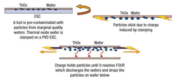
Figure 1. Hypothesis of particle showering due to electrostatically adhered particles to thermal oxide wafers.

The International Technology Roadmap for Semiconductors (ITRS) provides guidelines for both the number of allowable backside wafer particle adders and also the size of the adders. The size of particle adders identified as killer defects in the 2009 ITRS update [1] are 140nm on the back side and 25nm on the front side for back-end-of-line (BEOL), with stricter guidelines for front-end-of-line (FEOL). Because electrostatic attraction is known to cause both particle attraction and adhesion, the 2008 ITRS update [2] guides equipment manufacturers to limit the maximum static charges on wafer surfaces to a corresponding electric field of 70V/cm for the 65nm node, and 50V/cm for 45nm. Static charge audits performed in production fabs frequently report oxide wafer field voltages as high as 2kV/cm, much higher than the ITRS-recommended limits. Ionization is an industry-recognized method for neutralizing static charges in cleanrooms to reduce particles. In-tool ionization is a way to reduce static charge on the wafer to safe levels that will prevent the electrostatic attraction and subsequent particle adhesion.

The authors describe an in-tool study performed in a Novellus INOVA NExT tool that used ionizers to reduce backside particles [3]. Upon transfer to the FOUP, particles electrostatically adhered to the wafer back side were released onto the wafer located directly below the contaminated one. By using ionizers to neutralize the electrostatic charge prior to moving the wafer into the FOUP, showering and contamination were almost eliminated. The study looked at effects with different clamping voltages and methods of static discharge, including conductive cones and two ionizer types and locations.

SEM and EDX images of the particle adders on the cross-contaminated wafers showed silicon and oxygen signatures, indicating these particles were silicon oxide particles. In this study, the amount of particle adherence and showering is related to oxide thickness and wafer quality.

It was hypothesized that a tool, exposed to the marginal quality "dummy" wafers used for particle monitoring, becomes contaminated with small insulating particles. While particle monitoring wafers retain some residual charge after clamping in PVD modules, oxide wafers retain surface charge even longer, especially when the oxides are thick. The surface charges, which also exist on the back side of the wafer, electrostatically attract and hold some of these small insulative/dielectric particles. Oxide wafers in the tool thus act as particle getters and then carry particles to the FOUP, where the wafers are partially discharged through the static dissipative liner. The static charge reduction combined with FOUP movement causes the particles to overcome Vanderwaal’s forces and gravity, resulting in the loose particles showering on the wafer situated in a lower slot in the same FOUP, creating a particle excursion (Fig.1).

To test this hypothesis on the customer tool and validate the results, the study was performed at the customer site and also at Novellus. The wafers included both particle-/thickness-grade bare silicon wafers and Tox wafers (thermal oxide on both surfaces) with different oxide thickness values ranging from 1 to 20kA. The Novellus-recommended clamping voltage was kept unchanged in the mechanical wafer processing recipe (also known as per wafer pass [PWP] recipe). The difference between the PWP and in-film recipes is that the PWP recipe does not use any power (no DC, no RF).

Metrology measurements were performed using a Surfscan SP1. Electrical charge measurements were performed using a Faraday FOUP, manufactured by ION Systems. ION Systems Model 4632 Air-assist QuadBar (QuadBar), Model 5630 MP AeroBar, (MP AeroBar), and Model 5225 AeroBar (AeroBar) ionizers were used during this study.

When studying the physics of particle attraction, calculations show that the deposition velocities of submicron particles are controlled more by electrostatic forces than gravitational forces [4]. A stationary particle of 100nm diameter (d), having its center at a distance d away from the backside of a neutral oxide-wafer surface with a charge of just 100 electrons on the particle surface will be more affected by electrostatic forces than gravity. According to Coulomb’s law, electrostatic force (F) on a particle is 
 
F = q2/(4πε0R2)

where, q is the amount of charge, ε0 is the permittivity of free space, and R is the distance of separation. Using image charge technique (R = 2d), the coulombic attractive force is 5.76 x 10⁻¹¹ N. The charge density on the particle surface is 3.2 × 10⁷ electrons/cm2.

Assuming that the 100nm-diameter particle with 100 surface electrons is made of SiO2 (bulk density 2634kg/m3), the gravitational force on this particle is 1.35 × 10⁻¹⁷ N. Since the gravitational force is much smaller than the calculated attractive force, the particle will get attracted to the surface.

In the frontend of a processing tool, charged particles that move near an already triboelectric charged SiO2 wafer backside have a high probability of being electrostatically attracted at high velocity rates and adhering to the wafer backside. The attractive force for smaller particles (smaller R) drastically increases as the image charge separation distance reduces. Thus, for smaller particle sizes, the binding force is even higher.

Ionizers neutralize all moving particles and wafer surfaces (including the wafer backside), reducing the chances of particle adhesion. In the case of already adhered particles on a wafer surface, ionizers can reduce the electrostatic forces holding these particles by effectively neutralizing charged surfaces. These loosened particles are then disrupted by gravity, wafer movement, and ionizer air-flow, allowing them to fall off before the wafer reaches the FOUP. To effectively remove particles that are adhered to a surface, surfaces must be neutralized as quickly as possible before the particles start to bond and exchange electrons.

Ionizers used to neutralize static charge should be chosen based on the application. Ionizers have different ion output densities and performance is measured by reporting the discharge time, the number of seconds required to reduce the potential of a charged plate monitor from ±1000 to 100V. The discharge time is dependent on ion density and external conditions such as air flow and humidity. Since a charged insulative (SiO2) wafer can have surface voltages in the kilovolts, an ionizer must have a high ion density to effectively reduce the charges to the SEMI spec values.

The study consisted of two phases: an experiment to identify the particle gettering and showering dependence on the oxide thickness, and testing to determine the effectiveness of conductive cones inside the process chamber and ionization in the mini-environment on reducing the static charge.
Click to Enlarge
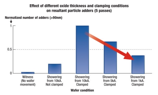
Figure 2. Dependence of showering particle adders on wafer oxide thickness. A low witness value indicates clean mini-environment and good experimental control. Non-clamped low value indicates that the non-electrostatic particle adders were well contained. A lower value of particle adders for thinner oxide indicates thicker oxides’ higher capacity to hold more charges therefore attracting more particles on the wafer backside, and resulting in more showering on the wafer in the lower slot of the FOUP.

The oxide thickness test was performed with oxide wafers separated by bare silicon particle-grade wafers (called the "showering" monitor wafers). The oxide thickness values used were 10, 5, and 1kA. Fig. 2 indicates a strong relationship between the charge-holding capacity of oxides, which is dependent on the oxide thickness, and particles showered by different oxide thicknesses. This observation supports the hypothesis.
 
The second phase of the test involved methods to reduce the static charge on the wafer and determine the resulting effect on particles. The first modification was to replace the ceramic cones contacting the wafer backside at a few locations in the load-lock module with customer-made doped zirconia conductive ceramic cones. The second hardware modification was to install three QuadBars to ionize the backside of the wafer when entering the mini-environment from the process. For a final production tool design, the QuadBars may be replaced with an MP AeroBar to reduce the ionizer footprint. The third modification was to install two AeroBars under the ULPA filter as topside ionizers.
Click to Enlarge
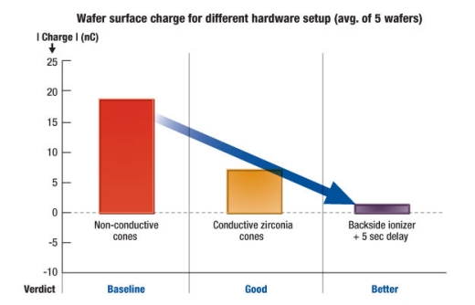
Figure 3. Wafer surface charge reduction with different hardware modifications such as conductive ceramic cones and backside ionizer installation.

As shown in Fig. 3, a baseline charge of ~18nC was reduced to 7nC by using conductive cones in the PVD tool load-locks. However, electrostatic attraction forces still existed and insufficient particle performance improvement was realized. The residual wafer charge was reduced to values below 2nC by using the backside ionizers and a 1min delay for testing purposes.

Click to Enlarge
Figure 4. Effect of ionizer assembly and delay on showering particle adders.

The delay helped to effectively discharge the surface, allowing the adhered particles to fall off in the mini-environment instead of in the FOUP (Fig. 4). It was observed that, with this configuration, the wafer frontside did not receive the benefit of ions generated by the backside ionizers, therefore the topside AeroBars were also turned on, which reduced the wafer charges to zero or near-zero values.
Click to Enlarge

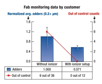
Figure 5. Particle monitoring data of a fab tool exposed to dummy wafers with marginal quality and during process wafer runs.

Testing on an in-fab PVD tool showed that with both sets of ionizers installed, particle adders dropped from nearly 30 to less than 5 for multiple wafers. When the PVD tool was exposed to dummy wafers having marginal quality, the average adders were reduced by ~50% (Fig. 5); more importantly, though, the out-of-control (OoC) rate went down from 6 out of 36 to 0 out of 11 particle qualification data points. An approximately 60% particle reduction, even from low showering counts, was achieved by using the ionizers. Zero counts were obtained 50% of the time and the ionizer reduced backside showering consistently. Repeat measurements on a Novellus lab tool not exposed to marginal wafer quality confirmed this result with nearly a 50% reduction on 6 wafers (data not shown).

The average adders of multiple wafers were reduced significantly in the presence of both sets of ionizers with the addition of a delay to allow the particles to fall off before the wafer reached the FOUP. When only the backside ionizers were used, static charge built up in multiple other locations inside the mini-environment, which led to electrostatic forces keeping insulating particles mobile. The topside AeroBar ionizers provided full mini-environment coverage that ensured all of the surfaces and particles remained neutral. The presence of both top and bottom ionizers is recommended for optimized performance.

Conclusion

Backside wafer particle contamination can be reduced or even eliminated through the use of optimized topside and backside ionization. Electrostatically attached particles are removed before the wafer is put into the FOUP, and are effectively carried away in the laminar flow, preventing particle showering on the front side of wafers in lower slots. An effective reduction of wafer backside particles in a PVD tool can be achieved using optimized ionizer configurations.

REFERENCES:
1. ITRS Roadmap: http://www.itrs.net/Links/2006Update/FinalToPost/09_Interconnect2006Update.pdf Table 82a.
2. ITRS Roadmap Static Control: http://www.itrs.net/links/2005itrs/Linked%20Files/2005Files/Factory/Static%20Control%20Background05RevFINAL.doc 3. V. Pandit, E. Kuo; "Reduction of electrostatically adhered particles on wafer backside using ionizers," Advanced Semiconductor Manufacturing Conference (ASMC), 2010 IEEE/SEMI, pp.200-205, 11-13 July 2010.
4. D. W. Cooper, H.L. Wolfe, and R. J. Miller, "Electrostatic Removal of Particles From Surfaces", Particles on Surfaces 1, book, edited by K. L. Mittal, Plenum Press, New York & London, 1988.

Authors:
Viraj Pandit and Emery Kuo, Novellus Systems
Cheryl Avery, ION Systems

Subscribe to Solid State Technology/Advanced Packaging.

Follow Solid State Technology on Twitter.com via editors Pete Singer, twitter.com/PetesTweetsPW and Debra Vogler, twitter.com/dvogler_PV_semi.

Or join our Facebook group

January 18, 2011 — Strategy Analytics has released a report stating that the optoelectronics segment of the compound semiconductor industry continued to grow into the close of 2010, driven by trends like broader adoption of LEDs for general and automotive lighting applications, as well as increased performance demand by the optical transport market.

The recently published Strategy Analytics GaAs and Compound Semiconductor Technologies Service (GaAs) viewpoint, "Compound Semiconductor Industry Review September-November 2010: Optoelectronics, Materials & Equipment" captures significant product, financial, contract and technology announcements for optoelectronic companies during the September to November 2010 time-period.

"A good sign for this industry segment is the strength of new orders and revenue growth reported by makers of long-lead fabrication, manufacturing and test equipment, like Aixtron and Veeco," said Eric Higham, director of the Strategy Analytics GaAs and Compound Semiconductor Technologies Service. "Adoption of LEDs and higher performance for optical transport networks is fueling investment to meet demand and product development to meet new requirements."

This viewpoint summarizes financial reports from LED, LASER, photovoltaic, material and equipment vendors like IQE, Kopin, Oclaro, Cree, JDSU, Aixtron, Veeco and GigOptix. There are lists of more than 40 product announcements aimed at a variety of optical and photovoltaic applications. It also captures significant contract, technology, materials, expansion and employment developments in the industry.

Strategy Analytics provides market intelligence focused on opportunities and disruptive forces in the areas of automotive electronics and entertainment, broadband connected home, mobile and wireless intelligent systems and virtual worlds.

Copyright 2011 Close-Up Media, Inc. All Rights Reserved

Subscribe to Solid State Technology/Advanced Packaging.

Follow Solid State Technology on Twitter.com via editors Pete Singer, twitter.com/PetesTweetsPW and Debra Vogler, twitter.com/dvogler_PV_semi.

Or join our Facebook group